
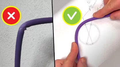
In fiber optic installations, the bending radius is a critical factor that’s often overlooked, but an improper bend can lead to signal attenuation.
This August, we are completing the FTTR (Fiber to the Room) service for the Hotel RIU Palace Aruba. Since we frequently encounter difficulties with cable threading inside the building, we recommended a bend-insensitive fiber optic cable model to the client. This type of fiber is specifically designed to navigate tight turns and conduits without compromising signal quality, and the solution was approved by the client.
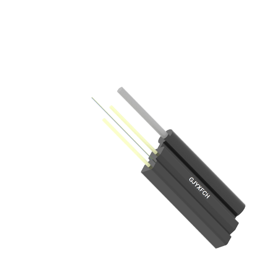
In the initial phase of the project, the client required a fiber optic cable that was flexible for easy threading through conduits and had an outer sheath with a CPR-Eca flame and fire-retardant rating. We recommended the GYFXZY-24B6a cable.
The client raised an objection to this structure, believing that the GYFXZY-24B6a’s small diameter of only 6mm made the cable appear insufficiently robust. They suggested using an ADSS structure instead.
This highlights a common misconception. Let’s compare the differences between ADSS and GYFXZY to clarify why they are used for completely different applications.
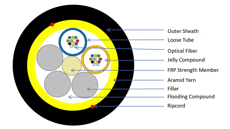
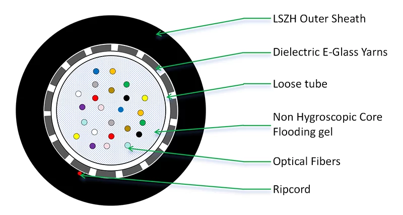
Due to the FRP central strength member and fillers, the inherent structure of ADSS cables has a large minimum bending radius, making them less flexible.In contrast, the central loose tube structure of GYFXZY cables allows for a much smaller bending radius. Therefore, ADSS is not suitable for in-building cabling.
Bend radius specifies the minimum curvature fiber cable can safely withstand without signal loss or physical damage. Maintaining proper bend radius ensures optimal light transmission and prevents micro-bending losses that compromise network performance.
Many technicians don’t realize that bending radius requirements are more than just suggestions—they are based on fundamental optical physics.
As an experienced fiber optic cable manufacturer, I know firsthand just how critical this parameter is. Allow me to share some of the key technical details and practical considerations that every project engineer should be aware of.
What Exactly Is the Definition of Fiber Optic Cable Bend Radius?
Field technicians frequently confuse bend radius with bend angles, leading to installation errors.
Bend radius is the minimum radius around which fiber cable can be bent without causing excessive signal attenuation or physical damage. It’s typically expressed as a multiple of the cable’s outer diameter and varies based on cable construction and application.
Comprehensive Technical Understanding of Bend Radius Specifications
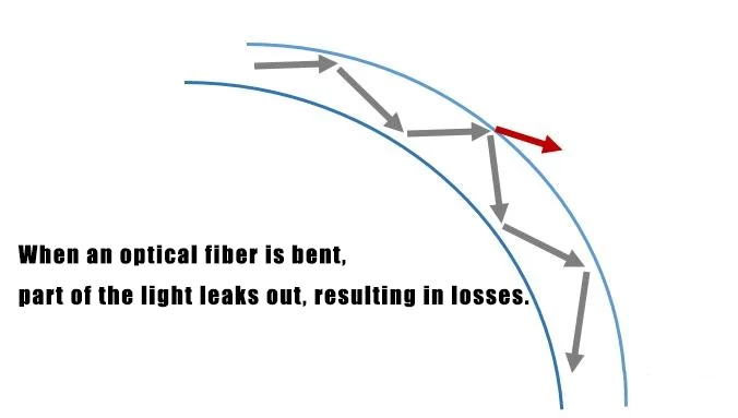
The science behind bend radius involves understanding light propagation physics. When light travels through a fiber, some light escapes through the cladding in what’s called evanescent wave. Bending the fiber too sharply accelerates this light loss through macrobending effects. Different fiber types have varying sensitivity to bending – single-mode fibers generally require larger bend radii than multimode fibers due to their smaller core size.
Several key factors influence bend radius requirements:
| Factor | Impact on Bend Radius | Practical Consideration |
|---|---|---|
| Cable Type | Tight-buffered cables allow smaller radii | Choose cable type based on installation path |
| Fiber Count | Higher fiber counts may require larger radii | Plan for extra space in congested areas |
| Installation Temperature | Colder temperatures require larger radii | Account for seasonal temperature variations |
| Installation Method | Dynamic installations need larger radii | Use different specs for pulling vs. final position |
| Operating Environment | Continuous stress requires conservative radii | Industrial settings need extra margin |
The consequences of ignoring bend radius specifications can be severe. Beyond immediate signal loss, excessive bending causes stress fractures that develop over time. I’ve documented cases where improperly bent cables failed completely after six months of operation despite initial testing showing acceptable performance.
Can I Bend Fiber Optic Cable at 90-Degree Angles?
Many installation scenarios require sharp turns, particularly in building risers and equipment racks. However, achieving 90-degree bends requires careful planning and execution.
Yes, you can create 90-degree bends, but only using proper bending techniques and maintaining the minimum bend radius throughout the turn. Specialized bend-insensitive fibers or mechanical aids like corner pulleys may be necessary for sharp turns.
Practical Implementation of 90-Degree Bends in Real-World Installations
Creating reliable 90-degree bends requires both technical knowledge and practical experience. First, calculate the actual space needed based on the cable’s minimum bend radius. For example, a cable with 1-inch diameter requiring 10× bend radius needs a 10-inch radius curve, meaning the turn will occupy significant horizontal and vertical space.
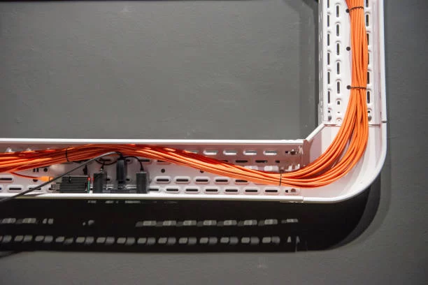
When space constraints prevent ideal bending, consider these solutions: Use pre-formed corner ducts or sweeping elbows that maintain constant radius, deploy bend-insensitive fiber specifically designed for tight spaces, or implement splices at corner points instead of continuous bending. I always recommend testing the completed bend with an OTDR to verify no additional attenuation has been introduced.
Documentation is crucial – note all sharp bends in installation records and include them in maintenance manuals. Future technicians need to know where these critical points are located to avoid further stress during modifications or repairs.
Understanding Fiber Optic Cable Bend Radius Tables
Bend radius specifications vary significantly across different cable types and manufacturers. Having a comprehensive reference table is essential for proper installation planning and execution.
Bend radius tables provide specific minimum curvature requirements for various cable types under different installation conditions. These tables are indispensable tools for design engineers, installers, and maintenance personnel to ensure compliance with manufacturer specifications.
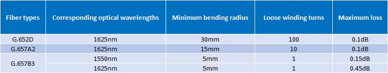
The International Telecommunication Union Telecommunication Standardization Sector (ITU-T) has defined the minimum bending radius for various types of optical fibers. The definitions of the minimum bending radius for the more common optical fibers are as follows:
Detailed Analysis of Bend Radius Table Applications and Interpretation
A proper bend radius table should differentiate between static (stationary) and dynamic (during installation) bend radii. Static bend radius applies to cables in their final installed position, while dynamic bend radius governs pulling operations and temporary positioning. Most manufacturers provide both values, with dynamic typically being 1.5-2 times larger than static requirements.
When using these tables, consider these practical aspects: Account for cable aging – some materials may become less flexible over time, consider temperature variations which affect material flexibility, and remember that bundled cables may have different requirements than individual cables. I always add a safety margin of 20-25% to published values for critical installations.
For design purposes, bend radius tables help determine pathway sizing requirements. If you’re designing cable trays or conduits, you must ensure they accommodate the required bend radii for all planned cables. This often becomes the limiting factor in dense installation environments.
Is Bend Radius the Primary Cause of Fiber Optic Cable Failures?
While bend radius issues contribute significantly to fiber failures, they’re rarely the sole cause. Understanding the complete failure landscape helps develop comprehensive prevention strategies.
Bend radius violations are among the top three causes of fiber failures, but they typically work in combination with other factors like mechanical stress, environmental conditions, or manufacturing defects. Proper bend management prevents approximately 40% of installation-related failures.
Comprehensive Failure Analysis and Prevention Strategies
Based on my analysis of hundreds of failure cases, bend-related issues account for about 35% of premature failures. However, these rarely occur in isolation. Most bend radius failures involve contributing factors like improper cable handling during installation, inadequate pathway design, or unexpected environmental changes.
The most common bend-related failure modes include: Microbending attenuation caused by pressure points against sharp edges, macrobending loss from sustained tight bends, and fiber fracture due to excessive stress during installation. These failures often have delayed onset – they might not appear during initial testing but develop over weeks or months.
Prevention requires a systematic approach: Implement rigorous training programs for installation teams, use proper bending tools and measurement devices, conduct thorough inspection of all bends during installation, and establish clear documentation standards. Regular maintenance should include bend radius verification, especially in areas subject to environmental changes or potential disturbance.
Conclusion
Maintaining proper bend radius is absolutely critical for fiber performance and longevity. Always follow manufacturer specifications and implement robust quality control measures throughout the cable’s lifecycle.