
1.Fiber optic connector appearance inspection.
| Inspection items | Inspection standards | Remarks | |
| Integrity | All parts are complete and consistent with the corresponding design and manufacturing requirements. The processing quality meets the requirements of relevant technical documents, and the test data, labels, and barcodes are correct. | ||
| Appearance | All components must be smooth, clean, and free of dirt, burrs, scratches, and cracks. They should have a bright, consistent color. The components should be firmly and evenly joined. The connectors should insert and pull out of the adapters smoothly and easily, and the clips should be strong, resilient, and function properly. The optical cable should be smooth and bright, free of impurities and damage, with clear printing, and the color should match the product requirements. | ||
| Optical cable length | Length (L) | Tolerance | Can be modified as per customer requirements. |
| L≤0.5m | +0.01/-0m | ||
| 0.5m<L<5m | +0.05/-0m | ||
| 5m≤L≤10m | +0.1/-0m | ||
| L>10m | +0.2/-0m | ||
| Identification | Apply a serial number label or a marking ring to the rear end of the strain relief boot, or leave it blank, as per order requirements. | ||
| Packaging | The packaging box should include the following: product name, model, production batch, production date, company’s registered trademark, executive standard number, environmental protection logo, and a product manual. The packaging itself must be complete and free of defects such as damage, crushing, deformation, or dirt. | Can be modified as per customer requirements. | |
2. Assembly Performance
2.1 Ferrule: Normal protrusion length, good elasticity, and a clear chamfer. The surface must be free of any dirt, defects, or other imperfections.
2.2 Loose Parts: Each loose part must fit well with the adapter without loosening. They should have good mechanical performance and mobility. The surfaces must be free of any dirt, defects, damage, or cracks. The color should match product requirements, with no chromatic aberration within the same batch.
2.3 Crimping: The crimping and fixation of the optical cable jacket and Kevlar fibers must be secure. The crimped metal parts should have a regular indentation, free of damage, bending, or improper squeezing of the cable.
3. End-Face Standard
Inspect according to Appendix 1, “Fiber Optic Connector End-Face Inspection Specification.”
4. Insertion and Return Loss Technical Standards
| Connector Model | FC,SC,LC,ST,MU,E2000,D4,DIN | |||
| Mode | SM | MM | ||
| End-face specification | PC | UPC | APC | PC |
| IL(dB) | ≤0.3 | ≤0.2 | ≤0.3 | ≤0.3 |
| RL(dB) | ≥45 | ≥50 | ≥60 | ≥35 |
| Other models | MT-RJ、MPO | |||
| IL(dB) | ≤0.7 | / | ≤0.7 | ≤0.5 |
| RL(dB) | ≥30 | / | ≥50 | ≥25 |
5. End-Face Geometry (3D) Standards.
| Item | PC、UPC | APC | ||||
| SC,FC,ST,E2000,D4,DIN | LC,MU | SC,FC,E2000 | LC,MU | |||
| SM | MM | SM | MM | SM | MM | |
| Radius of Curvature (mm) | 10-25 | 7-20 | 5-12 | |||
| Apex Offset | ≤50 | ≤30 | ||||
| Fiber protrusion/recession (nm) | ±100 | |||||
| Angle Deviation (°) | 0 | 8±0.3 | ||||
| Key Angle Deviation (°) | 0 | ±0.5 | ||||
| Fiber Diameter (µm) | 123-135 | |||||
6. Qualified Product Identification
Qualified product identification includes: serial number (each product has a unique one, consisting of the production plan number plus a sequential number), model number, barcode label (optional, based on customer requirements), product manual (optional), 3D report (optional), environmental protection label (optional), and insertion/return loss test data, etc.
7. Product Packaging
7.1 Basic Product Packaging: The fiber optic connector should be coiled into a circle with a diameter of 15-18 cm. The two ends of the connector should be secured with a cable tie symmetrically to the middle of the coil. Depending on the product model, the tie method can be a figure-eight (“8”) or a straight line (“1”) to prevent it from coming loose without leaving marks on the cable. For 0.9 mm cables, a snake-shaped tube is used for binding. Special models should be handled according to the corresponding “Packaging Operation Guide.” The bound connector should be placed head-down into its corresponding, pre-labeled packaging bag. The bag mouth should be sealed, and as much air as possible should be removed without deforming the connector.
7.2 Final Packaging: After basic packaging, the products are put into a shipping box in integer units. The inside of the box is partitioned with cardboard, bubble wrap, pearl cotton, or other anti-crushing protective materials. Special models should be handled according to the corresponding “Packaging Operation Guide.” After applying a packing list and other product labels to the outside, the box is sealed and placed in the designated finished goods area.
8. Technical Standards for Each Component
8.1 Ferrule:
8.1.1 The product complies with the following standards:
- YDT 1198-2002 “Technical Requirements for Fiber Optic Connector Ferrule”
- Telcordia GR-326-CORE
8.1.2 Detailed technical requirements can be found in Appendix 2, “Conventional Ferrule Technical Standards.”
8.2 Optical Fiber/Cable:
8.2.1 The product complies with the following standards:
- YDT 1258.1-2003 “Indoor Optical Cables Part 1: General”
- YDT 1258.2-2003 “Indoor Optical Cables Part 2: Simplex Cables”
- YDT 1258.3-2003 “Indoor Optical Cables Part 3: Duplex Cables”
- YDT 1258.4-2005 “Indoor Optical Cables Part 4: Multi-core Cables”
- YDT 1258.5-2005 “Indoor Optical Cables Part 5: Ribbon Fiber Cables”
- YDT 1258.3-2009 “Indoor Optical Cables Part 3: Simplex and Duplex Cables for Premises Wiring”
- YDT 908-2000 “Method for Naming Optical Cable Models”
8.2.2 Performance, dimensions, materials, color, and environmental protection conform to relevant national industry standards. The color of products within the same batch and model must be consistent.
8.3 Connector:
8.3.1 Product performance indicators comply with the following national standards:
- GBT 12507.1-2000 “Fiber Optic Connector Part 1: Generic Specification”
- GBT 12507.2-1997 “Fiber Optic Cable Connector Part 2: Sectional Specification for F-SMA Type”
- YDT 1272.1-2003 “Fiber Optic Patch Cords Part 1: LC Type”
- YDT 1272.2-2005 “Fiber Optic Patch Cords Part 2: MT-RJ Type”
- YDT 1272.3-2005 “Fiber Optic Patch Cords Part 3: SC Type”
- YDT 1272.4-2007 “Fiber Optic Patch Cords Part 4: FC Type”
- YDT 1272.5-2009 “Fiber Optic Patch Cords Part 5: MPO Type”
- YD987-1998 “Technical Specification for ST/PC Type Single-mode Fiber Optic Patch Cords”
- YDT 2152-2010 “Reliability Requirements and Test Methods for Fiber Optic Patch Cords”
8.3.2 Connector Loose Parts Color Chart:
| Fiber Optic Connector Models | SM | MM | ||||||||
| Structure | Outer Housing | Strain Relief Boot | Dust Cap | Heat Shrink Tube | Structure | Outer Housing | Strain Relief Boot | Dust Cap | Heat Shrink Tube | |
| FC/PC | SX,DX | Metal | Black | Colorless | / | SX,DX | Metal | Black | Colorless | / |
| FC/APC | SX,DX | Metal | Green | Green | / | SX,DX | / | |||
| SC/PC | SX,DX | Blue | Blue | Colorless | / | SX,DX | Beige | Beige | Colorless | / |
| SC/APC | SX,DX | Green | Green | Green | / | SX,DX | / | |||
| LC/PC | SX,DX | Blue | White | White | Yellow,White | SX,DX | BlueBeige | White | White | Yellow,White |
| LC/APC | SX,DX | Green | Green | Green | Yellow,White | SX,DX | / | |||
| E2000/UPC | SX,DX | Blue | Blue | / | / | SX,DX | Blue | Brown | / | / |
| E2000/APC | SX,DX | Green | Green | / | / | SX,DX | / | |||
| MU/PC | SX,DX | Brown | Blue | Black | / | SX,DX | Brown | Blue | Black | / |
| MU/APC | SX,DX | Green | Green | Green | / | / | ||||
| ST/PC | SX,DX | Metal | Black | Colorless | / | SX,DX | Metal | Black | Colorless | / |
| MT-RJ | multi-core | Black | Black | Colorless | / | multi-core | Black | Black | Colorless | / |
| MPO/PC | multi-core | Yellow | Black | Black | / | multi-core | Beige | Black | Black | / |
| MPO/APC | multi-core | Green | Black | Green | / | multi-core | / | |||
| D4 | SX,DX | Metal | White | Colorless | / | SX,DX | Metal | White | Colorless | / |
| DIN | SX,DX | Metal | White | White | / | SX,DX | Metal | White | White | / |
Appendix I: Fiber Optic Connector End-Face Inspection Specification
1.Inspection Equipment: 400X end-face inspection microscope with a monitor.
2.End-Face Requirements:
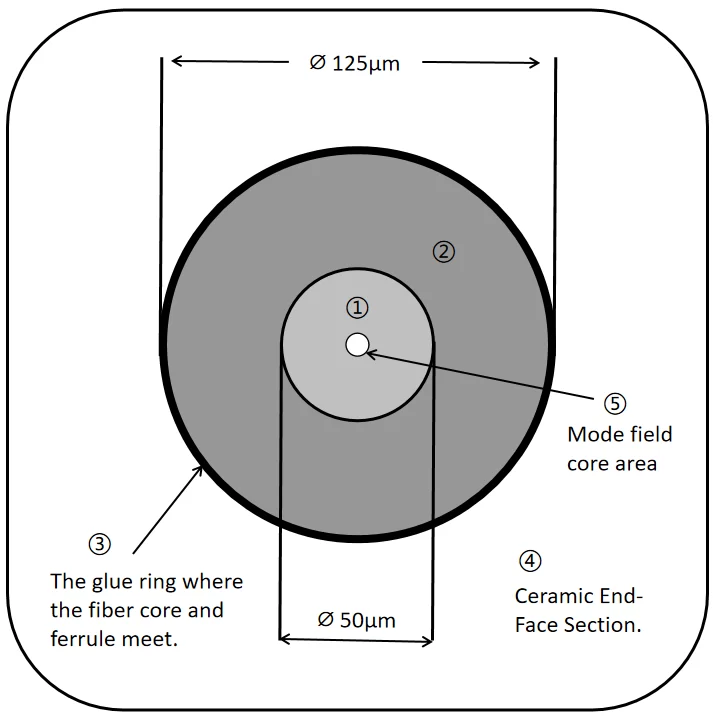
| Regional range | Description of defect | Grade A End-Face Inspection Standard |
| Within a ⌀50 µm diameter | Scratches,Spots,Bubbles,Black spots,Cracks,Dirt | No negative defects are allowed. |
| Within a diameter of 50-125 µm. | ||
| O-ring | Black spots/blocks, unevenness, spots, cracks, and dirt. The size must not exceed 1/4 of the fiber core and the width must be no greater than 1 µm. | |
| Ceramic end-face part (visible area outside the O-ring). | Scratches,Spots,Bubbles,Black spots,Cracks,Dirt | |
| Mode field core area. | No cracks, scratches, patches, or shadows. Light transmission is good, with a clear light spot. |
3.Fiber Optic End-Face Diagram
Appendix II: Conventional Ferrule Technical Standards
I. Product Technical Standards
- Ferrule Material: Made of Zirconium Dioxide (ZrO2) powder, an opaque milky white color that complies with the RoHS standard.
- Chemical Composition:
| ZrO2(Wt%) | ≈94.3 |
| Y2O3(Wt%) | 5.40±0.20 |
| A12O2(Wt%) | 0.25±0.05 |
| SiO2(Wt%) | ≤0.03 |
| Na2O(Wt%) | ≤0.01 |
| Fe2O3(Wt%) | ≤0.01 |
II. Ferrule Specification Types and Dimension Requirements
1.Conventional Ferrule Specification Classification (Model Specification Classification)
| SC Type | SC/SM/PC |
| SC/MM/PC | |
| SC/SM/APC | |
| LC Type | LC/SM |
| LC/MM |
2. Technical Requirements:
| SC Type | |||
| Item | Unit | Specification | |
| SM | MM | ||
| Out Diameter | mm | ⌀2.4990 ±0.0005 | |
| Concentricity | mm | ≤0.0014 | ≤0.004 |
| Inner Diameter | mm | ⌀0.125~0.126 | ⌀0.127~0.130 |
| Appearance of Endface | / | Roundness and appearance are qualified. | |
| Length | mm | 10.50±0.05 | |
| LC Type | |||
| Item | Unit | Specification | |
| SM | MM | ||
| Out Diameter | mm | ⌀1.2490 ±0.0005 | |
| Concentricity | mm | ≤0.0014 | ≤0.004 |
| Inner Diameter | mm | ⌀0.125~0.126 | ⌀0.127~0.130 |
| Appearance of Endface | / | Roundness and appearance are qualified. | |
| Length | mm | 10.50±0.05 | |
| Diameter of Endface | mm | ⌀0.60±0.15/-0 | |
| Degree of front chamfer | ° | 35°±2.5° | |
3.Tail-end Specification
| Optical Fiber Ferrule Specifications | Tail-end Specifications | Protrusion length | Withdrawal Force |
| SC/PC | Stainless steel SUS303 or nickel-plated copper, slot width 1.5 mm | 7.95±0.05/0 | >50N |
| SC/APC | Stainless steel SUS303 or nickel-plated copper, slot width 1.35 mm | 8.10±0.05/0 | |
| LC/PC | Stainless steel SUS303 or nickel-plated copper | 4.95±0.05/0 | |
| LC/APC | 5.10±0.05/0 | ||
| ST/PC | 7.95±0.05/0 |