Blog
Popular Blogs
- Building A, Republic International Business Plaza, No. 3699 Gonghexin Road, Jing'an District, Shanghai
- +86-21-59175887
- market@soctfiber.com
- 86-17321363317
- 86-13341796231
ODF, Coupler, Terminal Box & Pigtail in Fiber Optics
In our fiber optic projects, the products we work with most frequently are optical fibers and fiber optic cables. Many of our colleagues often mention the use of devices such as the Optical Distribution Frame (ODF), Fiber Optic Coupler, Fiber Optic Terminal Box, and Fiber Optic Pigtail.
In particular, the fiber splicing color code sequence is something that frequently comes up during installation and maintenance.
In this issue, let’s take a closer look at how these common devices are applied and differentiated in fiber optic projects.
1. Optical Distribution Frame (ODF)

The Optical Distribution Frame (ODF) is mainly used in optical fiber communication systems for the termination and distribution of backbone optical cables at the central office. It allows for easy connection, distribution, and scheduling (management) of optical fiber lines.
Compared with a fiber optic terminal box, the ODF has a more refined appearance. It features a metal frame enclosure with integrated fiber management trays inside. The trays are equipped with fiber optic adapters (couplers) and pigtails.
Depending on the connector type, ODFs can include FC, ST, LC, or SC adapters and corresponding pigtails. The pigtails can be ribbon pigtails or patch cords assembled to suit project requirements.
Common ODF configurations include 12-core, 24-core, 48-core, 72-core, 96-core, and 144-core models. ODFs with larger capacities are generally classified as fiber cross-connection cabinets (FDTs).
ODFs are typically installed in main equipment rooms or central offices, where both appearance and reliability are important.
In contrast, fiber optic terminal boxes are more often used in small monitoring rooms or weak-current distribution boxes, where maintaining a stable link is the main priority, and aesthetics are secondary.
2. Fiber Optic Coupler
A Fiber Optic Coupler, also known as a fiber adapter or fiber flange, is a device used for removable (active) connections between two optical fibers. Its main function is to precisely align the end faces of two fibers, so that the light energy from the transmitting fiber is maximally coupled into the receiving fiber, while minimizing the impact on the optical link and the overall system performance.
2.1 Classification by Fiber Connector Type:
- SC Fiber Optic Coupler: Used for SC connectors. If the coupler has 8 thin copper pins, it is an RJ-45 interface; if it has a single copper post, it is for SC fiber connectors.
- LC Fiber Optic Coupler: Used for LC connectors, typically connecting SFP modules; commonly used in routers.
- FC Fiber Optic Coupler: Used for FC connectors, generally installed on the ODF side.
- ST Fiber Optic Coupler: Used for ST connectors, commonly installed in fiber distribution frames (ODFs).
2.2 Functions of Fiber Optic Couplers:
- Low insertion loss – Minimizes signal attenuation.
- Coupling multimode signals into single-mode fibers when required.
- Ensures optical continuity by aligning fiber cores between two connectors.
- Allows optical signals from two fibers to communicate efficiently.
Fiber optic couplers are generally used in fiber optic terminal boxes, ODFs, and fiber cross-connection cabinets.
In telecommunications or security system projects, it is essential to use high-quality fiber optic couplers to ensure minimal link loss, thereby guaranteeing the normal operation of optical communication equipment.

3. Fiber Optic Terminal Box
A Fiber Optic Terminal Box is primarily used to protect bare optical fibers and pigtails. One end connects to the terminated optical cable, while the other end connects to the pigtails, effectively serving as a protective device that splits a fiber optic cable into individual fibers.
When installed on walls or in equipment racks, the terminal box provides:
- Fiber-to-fiber splicing
- Fiber-to-pigtail splicing
- Fiber connector interfacing
- Mechanical and environmental protection for the fibers and their components.
Common Specifications:
- Port capacities: 4, 8, 12, 24, 48, etc.
- Port types: semi-circular, rectangular, universal, FC rectangular, or straight exit.
- Fiber adapters (also called couplers or flanges) typically include FC, ST, SC, or LC types.
Form Factors:
- Desktop terminal boxes: Usually 4 or 8 ports; after splicing, they can be mounted on walls, placed on desktops, or installed inside enclosures.
- Rack-mounted terminal boxes: Usually 12, 24, or 48 ports; after splicing, they are installed in equipment racks or cabinets.

The internal structure of a fiber optic terminal box includes:
- Fiber management trays for organizing and storing pigtails,
- Cable entry ports for securing incoming optical cables,
- Adapter (coupler) mounting slots, and
- Cable strength member securing bolts.
For terminal boxes with a larger fiber count, the fiber management trays can be stacked in multiple layers to accommodate all fibers.
In terminal boxes that output pigtails directly, rubber grommets are installed at the pigtail exit to prevent damage to the fibers from the metal enclosure.

The pigtails used in fiber optic terminal boxes should be selected according to the type of communication equipment or optical cable, such as single-mode fiber, multi-mode fiber, or multi-mode 10G fiber (OM3).
In general, the fiber optic couplers, pigtails, patch cords, optical cables, and optical communication equipment should all be compatible with each other to ensure low-loss transmission and reliable signal reception.
4. Fiber Optic Patch Cord

A Fiber Optic Patch Cord (also called a fiber optic jumper) is an optical cable with connectors installed on both ends, used to achieve active optical connections between devices.
- In multi-mode fibers, the core diameter is typically 50 μm or 62.5 μm, roughly the thickness of a human hair.
- In single-mode fibers, the core diameter is approximately 9 μm.
4.1 Types of Fiber Optic Patch Cords:

- FC Patch Cord:
- Features a metal housing for reinforcement.
- Secured with a screw-type connector.
- Commonly used on the ODF side and in fiber distribution frames.
- SC Patch Cord:
- Connects to GBIC optical modules.
- Rectangular housing with a push-pull latching mechanism, no rotation required.
- Frequently used in routers, switches, and transceivers.
- ST Patch Cord:
- Commonly used in ODFs and fiber distribution frames.
- Round housing with a bayonet-style twist lock.
- For 10Base-F connections, ST connectors are typically used.
- LC Patch Cord:
- Connects to SFP optical modules.
- Modular design with easy-to-operate latch mechanism.
- Widely used for optical modules in networking equipment.
4.2 Fiber Color Coding:

- Single-mode Fiber (SMF): Patch cords are usually yellow, with blue connectors and protective boots, suitable for long-distance transmission.
- Multi-mode Fiber (MMF): Patch cords are usually orange, sometimes gray, with beige or black connectors and boots, suitable for shorter-distance transmission.
5. Fiber Optic Pigtail
A Fiber Optic Pigtail (also called a “pig-tail cable”) is an optical fiber with a connector installed on only one end, while the other end is a bare fiber, which is spliced to another optical fiber. Pigtails are commonly used inside fiber optic terminal boxes to connect optical cables to optical transceivers, often together with adapters (couplers) and patch cords.
5.1 Types of Pigtails:
- Multi-mode Pigtail: Typically orange, operating at a wavelength of 850 nm, suitable for short-distance interconnections up to 500 meters.
- Single-mode Pigtail: Typically yellow, available in 1310 nm and 1550 nm wavelengths, supporting transmission distances of 10 km and 40 km, respectively.
5.2 Difference Between Pigtails and Patch Cords:

It is important to note that pigtails and patch cords are not the same:
- A pigtail has only one end with an active connector, while the other end is spliced to the fiber network.
- A patch cord (jumper) has connectors on both ends and can connect two active ports directly.
- Patch cords come in various connector types and may also be split into multiple outputs to serve as pigtails when needed.
6. Fiber Color Code Sequence
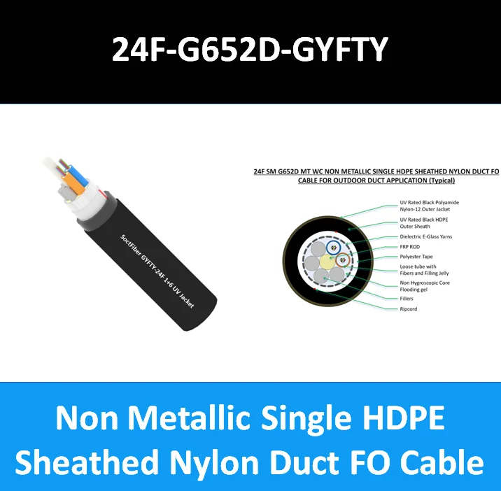
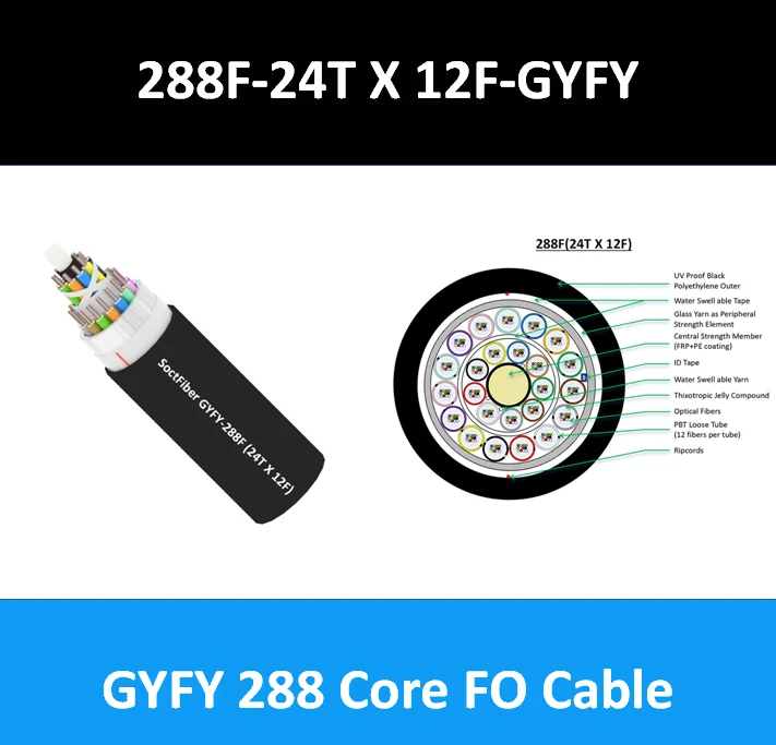
For optical cables with more than 12 cores, a layered stranded cable structure is commonly used. These cables consist of multiple sub-units (tubes), buffer tubes, and fibers, with each tube and fiber arranged according to a specific color code sequence.
For example, a 24-core cable may have four buffer tubes colored blue, orange, green, and brown, with six fibers per tube colored as blue, orange, green, brown, gray, and white.
For cables with fewer than 12 fibers, a single central buffer tube can accommodate all fibers, also called a central-tube cable. The fiber color sequence for fibers #1–12 is generally:
Blue, Orange, Green, Brown, Gray, White, Red, Black, Yellow, Violet, Pink, Aqua.

What is the natural color of optical fiber?
The 12 colors commonly seen in optical fibers (Blue, Orange, Green, Brown, Gray, White, Red, Black, Yellow, Violet, Pink, Aqua) are not the fiber’s natural color. They are color coatings applied to the fiber for:
- Identification — to distinguish each fiber within a cable.
- Mechanical reinforcement — to improve tensile strength.
The core material of the fiber is silica (SiO₂), which is naturally transparent. The colored coating is applied purely for management and protection purposes.
7. Conclusion
In fiber optic projects, understanding and properly using key components is essential to ensure efficient, low-loss optical transmission. From the Optical Distribution Frame (ODF) for structured cable management, to fiber optic couplers for precise signal connection, terminal boxes for protection and splicing, pigtails and patch cords for flexible connectivity, and the fiber color code sequence for correct identification, each element plays a critical role in the network.
Selecting the right components according to fiber type, connector type, and project requirements ensures reliable performance and long-term stability of optical links. By paying attention to these details, technicians and engineers can build high-quality, professional fiber optic networks that meet modern communication demands.


