
1.overview
The primary tensile strength members in an ADSS optical cable are the central strength member (CSM), typically made of Fiber Reinforced Plastic (FRP), and the reinforcement yarn, which is aramid yarn. The use of these tensile members prevents the internal optical fibers from bearing excessive strain when the cable is installed aerially, thereby mitigating the increase in additional attenuation. The Ultimate Tensile Strength (UTS) or Rated Breaking Strength (RBS) of the ADSS cable is one of the key indicators used to verify cable performance compliance. The methodology for ensuring adequate tensile strength varies depending on the cable’s structure and the required span length. Therefore, controlling the production process to guarantee the cable possesses the specified tensile strength is a crucial quality control metric.
2.Significance of ADSS Cable Breaking Strength and the Mechanism of Simultaneous Load Sharing
ADSS optical cables are suspended between support structures (poles/towers) with a specific sag over a given span length, which mandates high tensile performance. The cable’s breaking strength (RBS/UTS) is the defining parameter for its axial tensile strength, quantifying the effectiveness of the tensile members. A higher breaking strength indicates superior axial tensile resistance, better protecting the optical fibers from external forces that could lead to an increase in fiber strain and subsequent additional attenuation during operation. To achieve the maximum possible breaking strength, it is essential that all tensile members within the ADSS cable bear the load simultaneously. Due to varying levels of friction between components in different cable designs, distinct equipment, materials, and process control methods are required during manufacturing to ensure optimal tensile strength performance.
3. Guaranteeing Tensile Strength for Different Cable Structures
3.1 Primary Observations from Cable Breaking Strength Tests
The breaking strength test for ADSS optical cables simulates the mechanical environment during aerial installation. The test involves securing both ends of a cable sample with fittings (or grips), applying a tensile force to one end, and recording the maximum load at the moment of cable rupture, which is defined as the breaking strength or Ultimate Tensile Strength (UTS) [1]. An optical cable is composed of multiple components, including the central strength member, optical fibers, loose tubes, and an outer sheath. For ADSS cables, the primary load-bearing elements are the aramid yarn and the FRP (Fiber Reinforced Plastic) rod. Based on the breaking strength test results, the condition of these two elements typically exhibits three main outcomes:
(1) Observation One: Aramid Yarn and FRP Remain Intact (No Breakage) This scenario is typically caused by insufficient adhesion or compaction of the outer sheath around the aramid yarn. As the outer jacket stretches and neck-downs under tension, a slip occurs between the outer sheath and the primary tensile member (aramid yarn). Consequently, the aramid yarn and the FRP member do not effectively bear the axial load.
(2) Observation Two: Aramid Yarn Breaks, FRP Remains Intact This outcome suggests that the FRP only begins to bear the load after the aramid yarn has already reached its maximum strain limit and ruptured. Subsequent relative slippage occurs between the broken aramid yarn and the adjacent inner layer components, preventing the full transfer of the tensile force inwards. Therefore, the central strength member (FRP) remains unbroken. A special case involves most of the aramid yarn breaking while some aramid yarn and the FRP remain intact. This is often attributed to abnormal aramid stranding lay length, which results in non-simultaneous load-sharing among the aramid strands.
(3) Observation Three: Both Aramid Yarn and FRP Rupture This is the desired outcome, as it confirms that both the aramid yarn and the FRP provided their maximum tensile contribution. In this case, the cable’s breaking strength is optimized.
3.2 Determination of Inter-Component Friction in Optical Cables
The cable breaking strength test simulates the tension application during cable installation, where the cable is clamped at both ends by fittings. The fittings exert an inward gripping force F1. An axial tensile load F2 is applied to one end, and the maximum load at the moment of rupture is measured. Through stress analysis, it is understood that the cable tends to elongate in the direction of the applied F2. The tensile load is transferred sequentially from the outer layers to the inner layers, mediated by the gripping force F1. If relative slippage occurs between any two components within a layer, the force transfer to the inner components will be interrupted. These inner components will fail to contribute to the overall breaking strength and remain unbroken. Thus, ensuring adequate frictional force between all components is critically important.
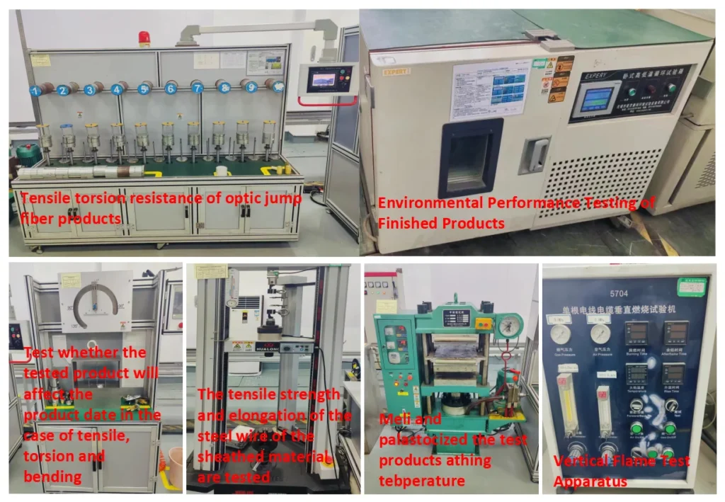
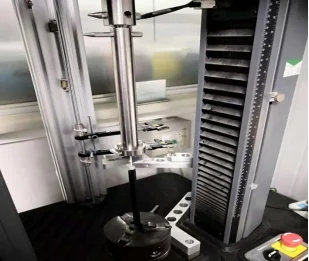
Our company utilizes an instrument capable of measuring the maximum static friction force between adjacent components. This device typically consists of a tensile testing machine, a component pull-out rod, a component clamping rod, and a gripping mechanism. It is designed to measure the peak static friction force immediately prior to the onset of relative movement (slippage) between the two tested components.
3.3 Guaranteeing Tensile Strength for Different Cable Structures
3.3.1 Addressing Anomalous Breaking Test Results
To prevent the anomalous situation of Observation One (Aramid Yarn and FRP remain intact), it is necessary to ensure the outer sheath has a sufficiently high capping force (or sheath integrity/tightness). Key control factors to achieve this include selecting appropriate die tip and die face dimensions, or increasing the distance between them to boost the extrusion pressure, and optimizing the processing temperature to enhance the sheath’s adhesion/compaction around the aramid yarn.
The occurrence of the Observation Two anomaly (Aramid Yarn breaks, FRP remains intact) is primarily caused by relative slippage between the FRP rod and the surrounding loose tube. This slippage significantly reduces the FRP’s contribution to the total tensile strength. This scenario is most commonly observed in Grease-Filled ADSS Optical Cables. Optical cables are categorized by water blocking method into filled (gel-filled) cables and dry cables [2]. We conducted breaking strength tests on both filled and dry cables, using identical equipment, materials, and process parameters, with the only difference being the water-blocking material (water-blocking yarns and tapes for dry cables versus filling grease/gel for filled cables). The test results are summarized in the table below: (The table is assumed to follow here).
| All-Dry Optical Cable | Gel-Filled Optical Cable | ||
| Tensile Strength (kN) | Cable Performance at Breaking Point | Tensile Strength (kN) | Cable Performance at Breaking Point |
| 19.6 | All cable components ruptured | 17.9 | All components ruptured except the Central FRP |
| 19.7 | All cable components ruptured | 18.1 | All components ruptured except the Central FRP |
| 19.4 | All cable components ruptured | 17.6 | All components ruptured except the Central FRP |
Based on Table 1, the observed breaking strength (tensile strength) of the gel-filled optical cable is lower than that of the all-dry optical cable. The cable performance at the breaking point for the filled sample, specifically, shows that the FRP rod remained intact (failure mode Observation Two). This suggests insufficient load sharing from the central strength member.
Consequently, we utilized our company’s Inter-Component Static Friction Tester to measure the friction force between the FRP rod and the adjacent loose tube components for both the dry and filled cables. The maximum friction force results, obtained under identical manufacturing conditions, are presented below:
| Experimental Sample 1 | Experimental Sample 2 | |
| Friction Force (N) between Loose Tube and FRP in All-Dry Cable | 88.6 | 91.2 |
| 88.3 | 90.8 | |
| 89.2 | 91.4 | |
| Friction Force (N) between Loose Tube and FRP in Gel-Filled Cable | 45.5 | 57.3 |
| 44.3 | 57.6 | |
| 46.7 | 57.4 |
The experimental comparison in Table 2 clearly shows that the friction force between the loose tube and the FRP rod in the gel-filled optical cable is significantly less than that in the all-dry optical cable (Friction Filled<Friction Dry).
This difference is attributed to the filling compound (cable gel) acting as a lubricant, which substantially reduces the friction between the two components. During the tensile (breaking strength) test, the insufficiently low friction force between the loose tube and the FRP rod causes relative slippage between them. Consequently, the FRP rod either fails to bear the axial load entirely, or it provides a significantly reduced tensile contribution.
3.3.2 Issue of Low Friction Between Loose Tube and FRP Rod in Gel-Filled Optical Cables
To prevent relative slippage between the loose tube and the strength member (FRP rod) and to effectively increase the friction force between these two components, improvements can be made from two main perspectives: processing technology and material modification.
(I) Process Improvement Perspective
The following breaking strength (tensile strength) results were obtained by only reducing the aramid yarn stranding pitch:
| Gel-Filled Optical Cable | ||
| Stranding Pitches (mm) | Tensile Strength (kN) | Sample Performance After Breaking Test |
| 650 | 16.8 | All cable components ruptured except the Central FRP. |
| 600 | 17.3 | All cable components ruptured except the Central FRP. |
| 550 | 17.7 | All cable components ruptured except the Central FRP. |
| 500 | 18.7 | All cable components ruptured. |
| 450 | 19.6 | All cable components ruptured. |
Based on the experimental results, it can be concluded that reducing the stranding pitch of the aramid yarn effectively increases the cable’s breaking strength (tensile strength).
This increase is due to the smaller pitch leading to a longer axial movement length under the grip force of the fittings. This prolongs the stress-bearing path of the aramid yarn, allowing the fitting grip force F1 to be transferred more effectively inwards. The ultimate goal is achieved: the FRP rod and the aramid yarn bear the load simultaneously.
However, considering the stability of the stranding cage equipment during the cable production process, the yarn stranding pitch cannot be set too small. Furthermore, when the aramid yarn stranding pitch is reduced, the cable strain increases accordingly, resulting in larger sag when the cable is installed aerially, and ultimately increasing the cable’s load burden.
(II) Material Modification Perspective
To increase the friction force between the loose tube and the strength member, the contact surfaces of these components can be intentionally roughened (made coarse). Research into this area primarily yields the following two methods for increasing the surface friction between the two components:
(1) Using Stranded/Helically Wrapped FRP (W-FRP) to Increase Friction:
This method involves simultaneously wrapping two glass yarns around the FRP surface during the FRP manufacturing process. The glass yarns protruding from the surface make the Wrapped FRP (W-FRP) significantly less smooth compared to conventional FRP, thereby increasing the friction.
(2) Adding a Coarse PE Cushion Layer to the FRP Surface:
Since the FRP surface is relatively smooth, a coarse PE cushion layer (Polyethylene Layer) is applied to its surface. This added coarse PE layer effectively increases the surface friction between the loose tube and the strength member (FRP).
| Gel-Filled Optical Cable | |||
| Friction Force with Loose Tube (N) | Tensile Strength (kN) | Sample Performance After Breaking Test | |
| Normal FRP | 55.7 | 42.3 | All components ruptured except the FRP. |
| Wrapped FRP | 188.2 | 48.7 | All components ruptured. |
| FRP + PE Cushion Layer | 71 | 45.4 | All components ruptured except the FRP. |
The experimental results clearly indicate that by using Wrapped FRP (W-FRP), the friction force between the loose tube and the strength member significantly increases. The breaking test sample then shows a rupture of all components, which suggests that both the aramid yarn and the FRP rod provided their maximum tensile contributions, resulting in an optimal (maximum) breaking strength.
The experiment successfully demonstrates that adopting Wrapped FRP effectively prevents the “slippage” phenomenon between the loose tube and the FRP, which otherwise causes the FRP to remain intact. This modification ensures that the gel-filled optical cable possesses a significantly higher tensile (breaking) strength.
4. Investigation of Stranding Pitch Settings for ADSS Cable Stranding Cages
4.1 Usage of the Stranding Cage Equipment
Aramid yarn is the most crucial tensile (load-bearing) element in an ADSS (All-Dielectric Self-Supporting) cable. During cable production, the aramid yarn is stranded (wrapped) around the cable core at a fixed pitch to minimize the length difference between various yarn ends. This is necessary to prevent a reduction in the cable’s Rated Tensile Strength (RTS) due to uneven yarn lengths.
The aramid yarn is fed from the payoff system using a stranding cage under a certain tension. Therefore, the stability of the stranding cage equipment is extremely important. Our company currently utilizes an Electromagnetic Coil Damping Electro-Control Stranding Cage. This system uses electromagnetic induction to ensure the aramid yarn is fed uniformly at a constant tension and a fixed stranding pitch.
When installing the aramid yarn bobbins, they must be uniformly distributed within the stranding cage to ensure proper wrapping roundness. When filler yarns are used alongside aramid yarns, the layer closest to the outer jacket must contain the maximum possible amount of aramid yarn, as it possesses a much higher relative tensile strength. Furthermore, when installing the bobbins, coarse and fine yarns must be alternated within the stranding cage to ensure the mechanical performance of the cable.
4.2 Investigation of Stranding Pitch Difference Setting between Inner and Outer Aramid Yarn Layers
When a large number of aramid yarns are required, multiple stranding cages must be used simultaneously to produce the ADSS cable. After the tensile test, the observation that some yarns remain unbroken is primarily due to a suboptimal pitch setting difference between the inner and outer stranding cages.
Therefore, the following experiment was conducted to investigate the pitch difference setting between the inner and outer layers of aramid yarn stranding cages:
| Relationship between Outer Yarn Pitch A and Inner Yarn Pitch B (mm) | Tensile Strength (kN) | Sample Performance After Breaking Test |
| A > B | 40.1 | All outer yarns ruptured; inner yarns and FRP remained intact. |
| A = B | 42.7 | Significant stratification in yarn break length observed; FRP remained intact. |
| A < B | 45.3 | All load-bearing components ruptured. |
The experiment demonstrates that when the Outer Yarn Stranding Pitch is less than the Inner Yarn Stranding Pitch (A<B), all components rupture and the maximum tensile strength is achieved.This outcome occurs because, under the grip force F 1
of the fitting, as the force is gradually transferred inward, the outer yarn bears the load before the inner yarn. When the Outer Yarn Pitch is greater than or equal to the Inner Yarn Pitch (A≥B), the outer yarn will reach its breaking elongation faster and rupture prematurely. This is due to being stressed earlier in the tensile test and having a relatively larger stranding pitch. This unequal stress distribution among the tensile elements results in a lower overall cable breaking strength.
5.Summary
To ensure the optical cable possesses a qualified (sufficiently high) breaking strength (tensile strength), it is essential to guarantee adequate outer sheath integrity through appropriate die selection and extrusion temperature settings, and to ensure the FRP rod contributes a sufficiently large tensile force by setting a proper aramid yarn stranding pitch, maintaining the correct inner and outer layer pitch differential, and utilizing novel strength member materials.