In the manufacturing process of fiber optic cables, the quality of the extrusion of the outer layer of the cable core is one of the decisive factors for the overall quality of the fiber optic cable. The sheath (or jacket) primarily serves to protect the cable core, ensuring that the optical fibers inside are free from damage during transportation, installation, and use, thereby maintaining stable transmission performance. Furthermore, the quality of the sheath directly impacts the cable’s mechanical properties, such as tensile strength, crush resistance, and impact resistance. This article mainly analyzes the quality issues that are prone to occur during the fiber optic cable sheath extrusion process, focusing on raw materials used, cable production equipment, personnel management, and process control.
I. What are the Sheath Materials?
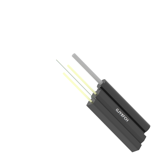
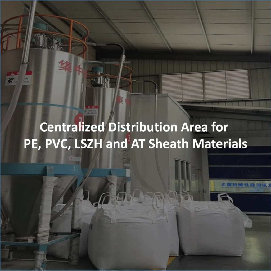
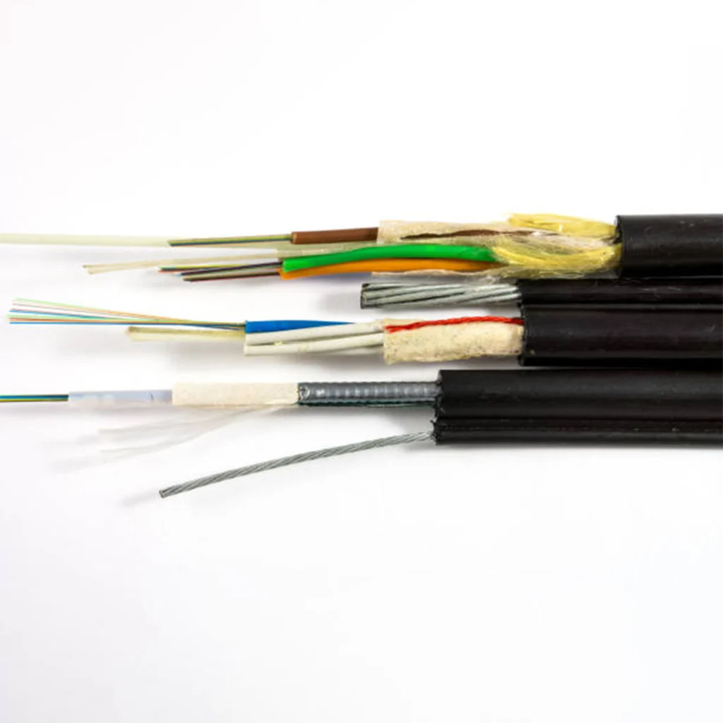
The sheath (or jacket) or outer protective layer is the outermost protective layer in the fiber optic cable structure, mainly utilizing PE sheathing compound and PVC sheathing compound. For special applications, Halogen-Free Flame Retardant (HFFR) sheathing compound and anti-tracking sheathing compound are used.

1. PE Sheathing Compound
PE is the abbreviation for Polyethylene, a high molecular weight compound polymerized from ethylene. Black polyethylene sheathing compound is made by uniformly blending and granulating polyethylene resin with stabilizers, carbon black, antioxidants, and plasticizers in certain proportions. Polyethylene sheathing compounds used for fiber optic cable sheaths can be classified by density into Low-Density Polyethylene (LDPE), Linear Low-Density Polyethylene (LLDPE), Medium-Density Polyethylene (MDPE), and High-Density Polyethylene (HDPE). Due to differences in density and molecular structure, they possess different properties.
Low-Density Polyethylene (LDPE) is also known as High-Pressure Polyethylene, polymerized through a co-polymerization reaction of ethylene under high pressure (above 1500 atmospheres) at a temperature of 200–300°C, with oxygen acting as a catalyst. Consequently, the molecular chains of LDPE contain multiple branches of varying lengths, resulting in a high degree of chain branching, less regular structure, low crystallinity, and good flexibility and elongation. High-Density Polyethylene (HDPE) is also known as Low-Pressure Polyethylene, polymerized from ethylene under low pressure (1–5 atmospheres) at a temperature of 60–80°C, using aluminum and titanium catalysts. Due to the narrow molecular weight distribution and orderly arrangement of molecules, HDPE exhibits better mechanical properties, good chemical resistance, and a wider operating temperature range. Medium-Density Polyethylene (MDPE) sheathing compound is produced by blending HDPE and LDPE in appropriate proportions, or by polymerizing ethylene monomer with propylene (or 1-butene as a second monomer). Thus, the properties of MDPE are intermediate between HDPE and LDPE, combining the flexibility of LDPE with the excellent abrasion resistance and tensile strength of HDPE. Linear Low-Density Polyethylene (LLDPE) is polymerized from ethylene monomer and 2-olefin using a low-pressure gas-phase or solution process. LLDPE’s degree of branching is between that of LDPE and HDPE, giving it excellent Environmental Stress Cracking Resistance (ESCR).
Environmental Stress Cracking Resistance (ESCR) is an extremely important index for evaluating the quality of PE materials. It refers to the phenomenon of cracking that occurs on a material test piece subjected to bending stress while immersed in a surfactant environment. Factors influencing the material’s stress cracking include: molecular weight, molecular weight distribution, crystallinity, and the microscopic structure of the molecular chain. The larger the molecular weight and the narrower the molecular weight distribution, the more connections there are between the crystallites, resulting in better ESCR performance and a longer service life for the material. At the same time, the material’s crystallization also affects this index; lower crystallinity leads to better ESCR.
The tensile strength and elongation at break of PE materials are another index for measuring material performance and can also predict the material’s service endpoint. The carbon content in PE material can effectively resist the erosion of ultraviolet (UV) light on the material, and antioxidants can effectively improve the material’s oxidation resistance. The performance of PE sheathing compounds of different densities must comply with Table 1.
Table 1: Performance of PE Sheathing Compounds of Different Densities
| Item | Unit | LDPE | LLDPE | MDPE | HDPE |
| Melt Flow Rate | g/10min | ≤ 2.0 | ≤ 2.0 | ≤ 0.7 | ≤ 0.5 |
| Density | g/cm³ | 0.92 ~ 0.94 | 0.92 ~ 0.945 | 0.932 ~ 0.950 | 0.950 ~ 0.978 |
| Tensile Strength | MPa | ≥ 13.0 | ≥ 14.0 | ≥ 18.0 | ≥ 20.0 |
| Elongation at Break | % | ≥ 500 | ≥ 600 | ≥ 650 | ≥ 650 |
| Low-Temperature Impact Brittleness Temp | ℃ | ≤ -76 | ≤ -76 | ≤ -76 | ≤ -76 |
| Environmental Stress Cracking Resistance | Fo(h) | ≥ 48 | ≥ 48 | ≥ 48 | ≥ 48 |
| Oxidation Induction Time 200℃ | min | ≥ 30 | ≥ 30 | ≥ 30 | ≥ 30 |
| Carbon Black Content | % | 2.6 ± 0.25 | 2.6 ± 0.25 | 2.6 ± 0.25 | 2.6 ± 0.25 |
| Carbon Black Dispersion | Score (分) | ≤ 6 | ≤ 6 | ≤ 6 | ≤ 6 |
| Volume Resistivity | Ω · cm | ≥ 10¹⁶ | ≥ 10¹⁶ | ≥ 10¹⁶ | ≥ 10¹⁶ |
| Dielectric Strength | MV/m | ≥ 25 | ≥ 25 | ≥ 25 | ≥ 25 |
2. PVC Sheathing Compound
PVC flame retardant material contains chlorine atoms; it will burn in a flame but decomposes to release a large amount of corrosive and toxic HCl gas during combustion, causing secondary harm. However, it self-extinguishes upon removal from the flame, thus possessing non-flame propagation characteristics. PVC sheathing compound also has good flexibility and elongation, making it widely used for indoor fiber optic cables.
3. Halogen-Free Flame Retardant (HFFR) Sheathing Compound
Because Polyvinyl Chloride (PVC) produces toxic gases when burned, a low-smoke, halogen-free, non-toxic, clean flame retardant sheathing compound was developed. This involves adding inorganic flame retardants, such as Al(OH)₃ and Mg(OH)₂, to ordinary sheathing compounds. When exposed to fire and burning, these compounds release water of crystallization while absorbing a large amount of heat, thereby preventing the rise in the sheathing compound’s temperature and stopping the combustion. The addition of inorganic flame retardants to HFFR sheathing compound increases the conductivity of the polymer. Furthermore, since the resin and inorganic flame retardant are two completely different phases of material, care must be taken during processing to prevent non-uniform local mixing of the flame retardant. The inorganic flame retardant must be added in an appropriate amount; an excessively large proportion will cause a significant drop in the material’s mechanical strength and elongation at break.
The indices used to evaluate the quality of the flame retardant performance of HFFR material are the Oxygen Index (OI) and smoke density. The Oxygen Index is the minimum oxygen concentration required for the material to maintain balanced combustion in an oxygen-nitrogen mixed gas atmosphere. A higher OI indicates better flame retardant performance of the material. Smoke density is calculated by measuring the transmittance of a parallel light beam through the smoke generated by the material’s combustion in a specific space and path length. Lower smoke density indicates less smoke generation and better material performance.
Table 2: Performance of PVC and Halogen-Free Flame Retardant Compounds
| Item | Unit | PVC (Typical Value) | Halogen-Free PE Sheathing Compound (Typical Value) |
| Tensile Strength | MPa | ≥ 15 | ≥ 15 |
| Elongation at Break | MPa | ≥ 150 | ≥ 150 |
| Low-Temperature Impact Brittleness Temp | ℃ | -20 | -20 |
| Oxidation Induction Time 200℃ | min | ≥ 60 | ≥ 60 |
| Volume Resistivity | Ω · cm | ≥ 10¹³ | ≥ 10¹¹ |
| Dielectric Strength | MV/m | ≥ 20 | ≥ 20 |
| Oxygen Index | % | — | 28 |
4. Anti-Tracking Sheathing Compound
In electric power communication systems, the use of All-Dielectric Self-Supporting (ADSS) fiber optic cables installed on the same towers as high-voltage overhead lines is increasing. To overcome the effect of the high-voltage induced electric field on the cable sheath, a new anti-tracking sheathing material has been developed and produced. This sheathing material achieves excellent anti-tracking performance by strictly controlling the content, particle size, and distribution of carbon black, and by adding special additives.
II.Quality Impacts Prone to Occur During Fiber Optic Cable Sheath Extrusion Due to Raw Materials Used in the Production Process

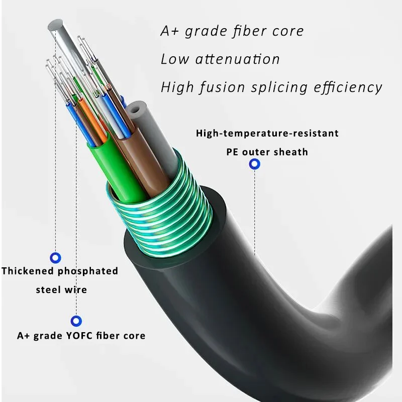
The quality of the raw materials used for the fiber optic cable sheath is a very important factor influencing the final sheath quality. Common polyethylene sheaths often have impurities such as sand particles, dust, inclusion of lower-melting point material, or insufficient drying. These issues can lead to phenomena like rough and uneven sheath surface, poor adhesion (sheath detachment), or intermittent ribbing and blistering. In central loose tube fiber optic cables, if the phosphated steel wires are rusted, or if the steel tape or water-blocking tape is damp, it can also cause quality issues such as sheath detachment and voids (air holes) in the cross-section.
III.Quality Impacts Prone to Occur During Fiber Optic Cable Sheath Extrusion Due to Process Control


To prevent quality issues during sheath extrusion, the production process must be strictly controlled to avoid quality problems caused by operational errors or negligence, thereby achieving the goals of reducing material consumption and cost, and improving product quality. Therefore, to prevent quality issues during fiber optic cable sheath extrusion, production operators must be strictly required to perform the following tasks through process control:
- Based on the production task: (Total quantity, number of reels, length per reel), strictly carry out all preparatory work according to the requirements of the fiber optic cable sheath extrusion process documents.
- Assemble the pressure mold, sizing die, and sheathing die prescribed in the process document and adjust the concentricity of the protective layer carefully. Arbitrary die matching can cause phenomena like bamboo jointing (uneven thickness) or sheath detachment during extrusion.
- Pay special attention to the following:
- When loading the cable core onto the payoff stand, carefully check if it is secure and if the tightening shaft is properly tightened. Check if the payoff is correct and smooth, and if the payoff tension adjustment is normal. Unstable payoff tension can cause the sheath to be intermittently thick and thin.
- The aluminum tape or steel tape reel must be installed stably and securely, and the tightening screws must be tightly fastened to prevent the reel from falling off during operation, which could cause tape breakage.
- The water-blocking compound (or filling grease) must be adequately filled but not excessively. The excess compound should be removed at the outlet of the filling device using two thin rubber strips (or one thick rubber strip). Before starting the machine, check the compressed air pressure; only start if it is normal.
- When producing central loose tube fiber optic cables with parallel steel wires, the payoff tension for both steel wires must be adjusted to ensure consistent tightness and stable running.
IV. Common Sheath Quality Issues and Solutions on the Production Line
| No. | Common Issues | Cause Analysis | Solution |
| 1 | Uneven outer diameter, bamboo jointing | 1. Outer die is too small, extrusion pressure is too high | 1. Select appropriate dies |
| 2. Uneven speed of payoff/take-up or capstan | 2. Check screw, capstan, and payoff/take-up | ||
| 3. Large variation in cable core outer diameter | 3. Control the screw and capstan | ||
| 4. Main machine belt is too loose or slipping | 4. Check the operation status of the machinery and electrical components | ||
| 2 | Composite tape has a scalloped edge/flange | 1. Forming die, sizing die, and die core are not accurately aligned on the same axis | 1. Ensure the collimation/straightness of the entire forming axis |
| 3 | Detachment or adhesive failure | 1. Cable core has water or oil | 1. Re-run after ensuring the quality of the cable core is properly handled |
| 2. Local temperature of the die is too low | 2. Appropriately increase the controlled temperature of the extruder head | ||
| 3. Steel (Aluminum) composite tape is loose, the joint is not secure or too large | 3. Select appropriately larger sheathing dies | ||
| 4 | Poor weld seam/fusion line | 1. Control temperature is too low, poor plasticization | 1. Strictly control temperature to ensure good plasticization |
| 2. Dies are severely worn | 2. Replace the dies | ||
| 3. Extruder head temperature control is too low, poor fusion | 3. Appropriately increase the controlled temperature of the extruder head | ||
| 4. Extruder head temperature control is too high, material viscosity is low | 4. Appropriately reduce the screw and capstan speed to prolong the plasticization time | ||
| 5. Insufficient extrusion pressure, plastic not tightly sealed inside the head | 5. Increase the filter screen, lengthen the forming length of the die, and increase the extrusion pressure |
V. Conclusion
For a long time, the two biggest drivers of development in the optical networking industry have been bandwidth demand and cost. That is, as bandwidth increases, there is a continuous requirement for the cost per bit to decrease. Therefore, fiber optic cable manufacturers like SoctFiber are required to continuously improve their process technology, strengthen equipment technical transformation or replacement, reduce material costs, and lower management costs to truly achieve high-performance and low-cost fiber optic cable production technology.