

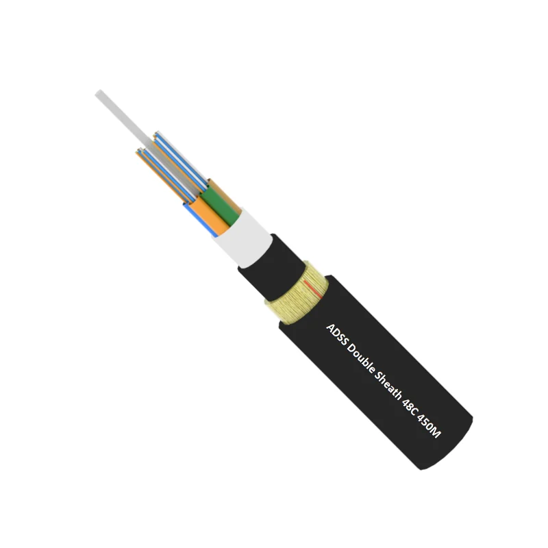
I. Characteristics of ADSS (All-Dielectric Self-Supporting) Fiber Optic Cable
- Live-line installation capability: ADSS cables are installed on the phase side of the transmission line, allowing deployment without power outages.
- Lightweight and compact design: The cable’s small outer diameter and low weight result in minimal additional mechanical load on poles and towers.
- Long span performance: Capable of spans up to 1200 meters, meeting requirements for wide river crossings and valley applications.
- Excellent electrical corrosion resistance: The polyethylene (PE) outer sheath provides superior tracking and corrosion resistance under high electric field conditions.
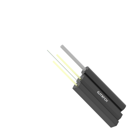
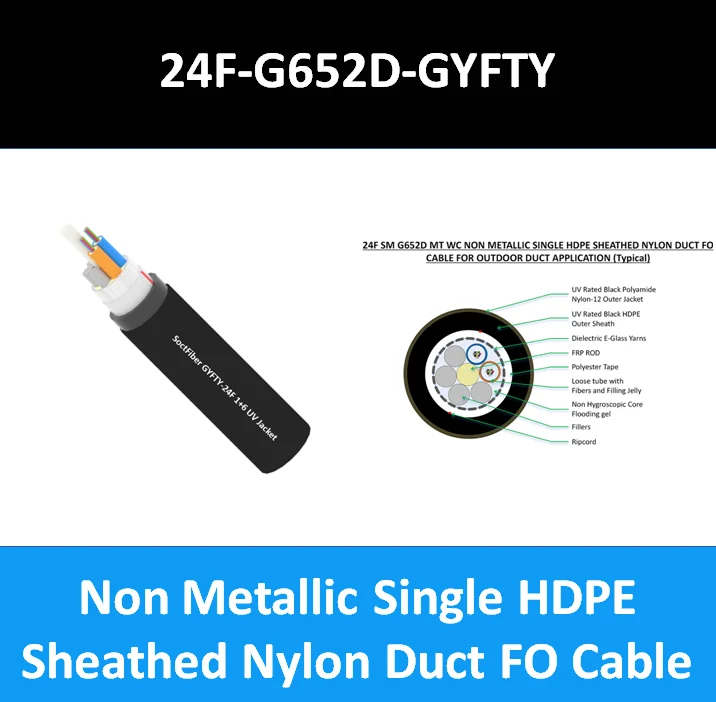
- All-dielectric structure: The non-metallic design ensures complete immunity to lightning-induced surges and electromagnetic interference.
- High mechanical and environmental reliability: Reinforced with aramid yarn (Kevlar®), offering excellent tensile strength, temperature stability, and wind/ice resistance, suitable for severe climatic regions.
- Long service life: Engineered for a typical operational lifespan exceeding 30 years under standard environmental conditions.

II. Preventive Measures for Common ADSS Cable Defects
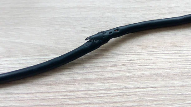
1. Outer Sheath Damage
Phenomenon:
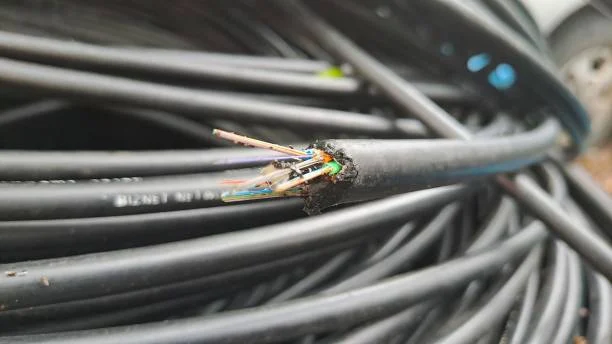
In hilly or mountainous terrain, ADSS cables may rub against rocks, tree branches, or sharp objects, leading to outer sheath abrasion, scratches, or deformation. A rough or damaged sheath is prone to tracking, electrical discharge, or corrosion in dusty or high-salinity environments, which accelerates cable aging and degradation.
Preventive Measures:
- Perform thorough inspection of cable drums and fittings before transportation and stringing.
- Ensure adequate supervision during installation (at least one qualified inspector on-site).
- Avoid dragging the cable on the ground or through vegetation; use protective rollers and guide sheaves during pulling.
2. Fiber Breaks and High-Attenuation Points
Phenomenon:
Fiber breakage and localized high loss points are typically caused by uneven tension or localized stress during installation. Non-uniform pulling speed, improper sheave diameter, or bending beyond the minimum bending radius may lead to microbending or macrobending losses.
Occasionally, the central FRP (Fiber Reinforced Plastic) strength member may fracture due to excessive tensile load. This results in structural deformation of the loose tubes and may lead to optical fiber failure.
Preventive Measures:
- Maintain constant and uniform pulling tension throughout the stringing process using tension-control equipment.
- Ensure smooth cable pay-off from the drum to prevent torsional stress.
- Verify that sheave diameters meet manufacturer recommendations to minimize bending stress.
- Conduct OTDR testing after installation to confirm no abnormal loss points.
3. Tensile Failure Near Dead-End Clamps
Phenomenon:
Tensile breakage at or near dead-end hardware (preformed dead-end grips) is one of the most common mechanical failures. It typically occurs within 1 meter of the clamp termination or occasionally behind the supporting structure.
Improper installation—such as incorrect preformed rod wrapping, insufficient grip length, or small pulling angle—can cause localized stress concentration, leading to fiber or FRP rupture.
Preventive Measures:
- Ensure correct alignment between the cable pulling direction and tension clamp orientation.
- Follow the manufacturer’s recommended installation procedures and preform pitch sequence.
- Avoid excessive pulling tension; use dynamometers to monitor real-time load.
- Inspect the dead-end hardware and armor rods for damage prior to installation.
III. Factors Influencing Electrical Corrosion of ADSS Fiber Optic Cables
1. Conventional Electrical Corrosion
When an ADSS cable is installed in the vicinity of a strong electromagnetic field, induced electromotive forces (EMF) are generated along the cable. The magnitude of this induced voltage varies significantly along the span — it tends to increase sharply near the termination of preformed rods and decrease progressively away from the tower structure.
As a result, severe electrical corrosion typically occurs at both ends of the span, rather than at the mid-span section. Under the influence of induced electric fields, an induced current ranging from 0.1 mA to 10 mA may flow along the sheath surface, which generally does not affect normal optical or mechanical performance of the cable.
2. Dry-Band Arcing
Due to potential differences in the surrounding electric field, leakage currents may flow across the surface of the ADSS cable’s outer sheath and the grounding fittings attached to the tower. The heat generated by these leakage currents causes local moisture evaporation, forming small dry bands on the sheath surface that interrupt the current path.
When the voltage across a dry band reaches a critical level, discharge occurs, forming a dry-band arc. The heat generated by the arc causes thermal degradation of the cross-linked polymer sheath, leading to carbonization, tracking, and pinhole formation — a process known as sheath electrical erosion (or electrical tracking). Over time, this can result in sheath perforation and eventual cable breakage.
Environmental factors such as dust, rain, snow, and airborne contaminants may also lead to the formation of a semiconductive pollution layer containing soluble salts. Under induced voltage, this layer promotes surface leakage currents, aggravating the electrical corrosion process.
3. Corona Discharge
The use of stockbridge dampers (vibration dampers) effectively mitigates aeolian vibration of ADSS cables and is typically installed outside the preformed armor rods. However, in areas with high electric field strength, the ends of the vibration dampers and preformed rods can act as discharge electrodes, resulting in corona discharge that accelerates sheath electrical erosion.
Non-uniform electric fields increase the probability of corona discharge. As discharge severity escalates, arcing may occur, producing localized carbonization or burning marks on the sheath. This not only weakens the mechanical integrity of the cable but may eventually cause fiber breakage or complete cable failure.
IV. Countermeasures for Mitigating Electrical Corrosion in ADSS Cables
1. Proper Selection of Cable and Fittings
Use of anti-tracking (AT) outer sheaths has been widely adopted in practical applications. These sheaths are made from non-polar polymer base materials with inorganic fillers that effectively isolate carbon black particles, minimizing leakage currents and preventing surface tracking.
Similarly, tracking-resistant polyethylene (TR-PE) sheath materials demonstrate enhanced thermal stability and resistance to dry-band arcing. Increasing the inorganic filler content to approximately 50% can further improve tracking resistance, though excessive filler may affect other mechanical or environmental properties.
The selected sheath material should provide high dielectric strength, UV resistance, and mechanical durability without compromising cable flexibility or long-term performance.
2. Optimization of Cable Attachment Points
Proper selection of suspension and dead-end locations is crucial to minimizing electrical corrosion and ensuring the operational reliability of the power communication network.
Scientific route planning and electromagnetic field analysis should be conducted to determine induced field distribution and intensity, allowing for optimal placement of attachment points that minimize electrical stress.
If discharge traces are observed primarily near fitting terminations, Stockbridge dampers may be used instead of spiral vibration dampers, preventing their tips from acting as discharge electrodes. Adjusting the attachment configuration helps to reduce corona generation and improve field uniformity.
3. Protection of Cable Surface
Strengthening surface protection measures during construction helps prevent sheath abrasion and contamination, which are precursors to electrical corrosion.
Comprehensive visual inspection should be performed before and after installation to detect surface scratches, cracks, or severe wear. Contaminants and surface moisture can lower insulation resistance, increase leakage current, and accelerate aging.
Before installation, conduct site surveys to identify adjacent obstacles such as poles, trees, buildings, or crossing structures, and ensure that the ADSS routing is laid out to avoid contact and mechanical damage.
Check the quality and integrity of protective sleeves and fittings, and ensure that the sheath exhibits adequate resistance to tracking and weathering.
4. Control of Preformed Rod and Vibration Damper Spacing
The spacing between preformed armor rods and vibration dampers must be properly controlled — this is a critical measure to prevent corona and electrical corrosion.
Excessive span lengths and high wind conditions can induce cable vibration beyond design limits. The number of vibration dampers should be selected according to the span length:
- 100–250 m: use one pair of dampers
- 250–500 m: use two pairs
- Over 500 m: increase to three pairs as required
Improper designs often overlook the minimum spacing requirement between the vibration damper and preformed rods, leading to corona discharge due to proximity. A minimum clearance of approximately 1 meter should be maintained.
During installation, use specialized tools to ensure correct placement and avoid accidental contact. Application of silicone-based insulating coatings can further enhance the surface insulation properties, suppress pollution flashover, and reduce corona discharge occurrences.
5. Installation of Corona Rings (Grading Rings)
The roughness and sharp edges of the preformed rod and vibration damper ends can act as corona initiation points, disrupting electric field uniformity and accelerating sheath degradation.
Installing corona rings (grading rings) at these points effectively reduces electric field concentration, raises the inception voltage for corona discharge, and thereby minimizes electrical erosion.
During installation, ensure that corona rings are properly positioned at the ends of preformed rods and dampers according to manufacturer specifications and relevant IEC/IEEE standards. The rings must not contact the cable sheath to prevent interference with cable performance.
V. Operation, Inspection, and Maintenance
- ADSS fiber optic resources shall be managed under the jurisdiction of the Provincial Power Communication Authority.
- Define the responsibility boundaries between power line maintenance units and optical network operation units.
- Notify all relevant departments in case of route modification, tower relocation, or system upgrade affecting the ADSS cable.
- Establish a regular patrol and inspection program, including checks for:
- Sheath tracking or surface discharge
- Corrosion and environmental degradation
- Proper integrity of suspension and tension fittings
- Install warning markers at crossing points and potential hazard locations.
- If any physical or electrical damage is detected, promptly coordinate with the design institute, manufacturer, and installation contractor to analyze root causes and formulate corrective actions.