

Fiber Optic Cable Engineering

Communication fiber optic cable engineering is mainly divided into aerial fiber optic cable engineering, direct-buried fiber optic cable engineering, duct fiber optic cable engineering, waterway fiber optic cable engineering, and submarine fiber optic cable engineering.
Table of Contents
- Overview
- Construction of Fiber Optic Cable Lines
- Single-Reel Inspection of Fiber Optic Cables
- Route Re-Survey of Fiber Optic Cables
- Cable Laying
- Splicing and Installation of Optical Cables
- Protection of Optical Cable Communication Lines
- Optical Cable Line Acceptance Standards
1. Overview
1.1 Characteristics of Fiber Optic Cable Line Construction
| Characteristic | Details |
|---|---|
| Fiber Optic Cable Length | The standard manufacturing length of general fiber optic cables is 2km (sometimes determined according to user requirements). For buried cables in ultra-long relay sections over 70km, the length is also 2km. |
| Low Tensile Strength | The tensile strength required by fiber optic cables is mainly borne by the strength members. The general tensile force of fiber optic cables is 100–300kg, while that of direct-buried cables is 600–800kg. For special fiber optic cables (such as underwater fiber optic cables), the tensile strength value is specified by the cable design department. |
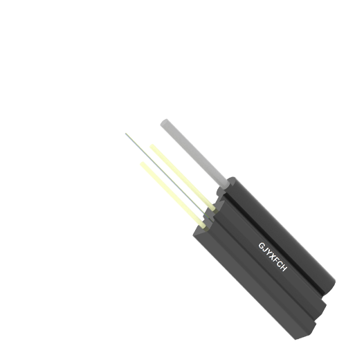
| Small Diameter & Light Weight | For example, single-mode fiber optic cables with fewer than 10 cores have a diameter within 11mm and a weight per unit length below 90kg/km. |
| High Requirements for Fiber Connection | Fiber splicing requires melting the fiber end faces at high temperatures and bonding them relying on the viscosity of quartz glass. Therefore, the equipment used for splicing is relatively complex, and the technical requirements are higher than those for cables. |
2. Construction of Fiber Optic Cable Lines
2.1 Scope of Fiber Optic Cable Line Construction
Fiber optic cable line engineering is an important part of fiber optic communication engineering. The division between it and transmission equipment installation engineering is based on the Optical Distribution Frame (ODF) or Optical Distribution Panel (ODP). The outer side of the ODF/ODP belongs to the fiber optic cable line part, i.e., the section between the connector of the local ODF/ODP (or the connector on the repeater) and the ODF/ODP (or the connector on the repeater) of the opposite station.
Schematic Diagram of Fiber Optic Cable Line Construction Scope
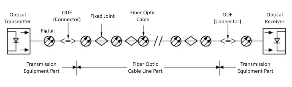
【Optical Transmitter → Pigtail → ODF (Connector) → Fixed Joint → Fiber Optic Cable → ODF (Connector) → Optical Receiver】
【Transmission Equipment Part— Fiber Optic Cable Line Part— Transmission Equipment Part】
Fiber optic cable line construction is further divided into the following scenarios:
- External Line PartThe construction content mainly includes laying fiber optic cables, implementing various protective measures after laying, and splicing the cables.
- Unmanned Station PartThe construction content mainly includes installing the unmanned repeater cabinet, introducing the fiber optic cable, terminating the cable, splicing all fibers in the cable with the pigtails of the connectors on the repeater, and connecting the copper conductors and strength members.
- Indoor Station Part① Laying indoor fiber optic cables.② Splicing all fibers of the cable with the pigtails of the ODF, ODP, or connectors on the repeater in the terminal equipment room and manned repeater room; and terminating and connecting the copper conductors, strength members, and protective ground.③ Final acceptance testing of the photoelectric indicators of the relay section.
2.2 Construction Procedure of Fiber Optic Cable Lines
The general construction procedure of fiber optic cable lines is divided into five phases: Preparation, Laying, Splicing, Testing, and Final Acceptance, as shown below:Single-Reel Inspection → Route Re-survey → Cable Reel Allocation → Route Preparation → Cable Laying → Splicing & Installation → Relay Section Testing → Final Acceptance
- Single-Reel Inspection of Cables: Check the appearance of the cable, relevant characteristics of the fibers, and signal wires.
- Route Re-survey: Based on the construction design drawing, recheck the specific route direction, laying conditions, environmental conditions, specific locations of joints, ground distance, cable reel allocation, and cable storage.
- Cable Reel Allocation: Calculate the total laying length based on the re-surveyed route and reasonably allocate the lengths of the cable reels.
- Route Preparation: For duct cables, clean the ducts and pre-lay iron wires or plastic conduits; for aerial cables, pre-lay steel strands and hooks; for direct-buried cables, dig cable trenches and set up joint pits. This ensures the smooth progress of the project and the safe laying of the cables.
- Cable Laying: According to the laying method, place the single-reel cable on utility poles (aerial), pull it into ducts (duct), or place it in cable trenches (direct-buried).
- Cable Splicing & Installation: Include fiber splicing, connection of copper conductors, aluminum sheaths, and strength members, measurement of joint loss, sealing of joint sleeves, and installation of joint protection devices.
- Relay Section Testing: Include testing of fiber characteristics (e.g., total fiber attenuation) and electrical performance of copper wires.
- Final Acceptance of Cables: Provide technical documents such as construction drawings, revised route maps, and measurement data, and conduct in-process inspection and final acceptance to deliver qualified fiber lines and ensure system commissioning.
3. Single-Reel Inspection of Fiber Optic Cables
3.1 Concept and Purpose of Single-Reel Inspection
- Mandatory Requirement: Single-reel inspection must be conducted before laying the cable.
- Inspection Work: Verify and count the specifications, types, and quantities of the cables and connection materials delivered to the site; conduct visual inspection and measure the main photoelectric characteristics. Confirm whether the quantity and quality of the cables and materials meet the requirements specified in the design documents or contracts.
- Significance: Single-reel inspection of cables has an important impact on ensuring the project schedule, construction quality, future communication quality, project economic benefits, maintenance, and line service life. Even if the schedule is tight, it must not be done hastily; instead, relevant technical regulations must be implemented with a scientific attitude, a strong sense of responsibility, and correct inspection methods.
3.2 Content and Methods of Single-Reel Inspection
- Collection of single-reel data (the data on the reel shall be included in the project final acceptance materials).
- Re-measurement of cable length (note the difference between fiber length and cable length).
- Measurement of single-reel loss of cables (determination of three methods).
- Inspection of cable sheath insulation.
- Inspection of other materials.
Single-reel inspection is suitable for on-site implementation, and the inspected cables and materials should not be transported over long distances. After inspection, records should be made for the cables and materials, and the reel number, outer end polarity, length, type (buried, duct, aerial, underwater, etc.), and application section (to be supplemented after reel allocation) should be marked on the cable reel.
3.2.1 Measurement of Single-Reel Loss of Cables
- Definition of Fiber Optic Loss: The attenuation of optical power during the transmission of optical signals along the fiber waveguide. The attenuation varies with the wavelength. The loss per unit length is called the loss coefficient, with the unit of dB/km. For single-reel inspection, the main task is to measure the loss coefficient.
- On-Site Measurement Methods and Selection:
- Cut-Back Method: A destructive method based on N measurements.
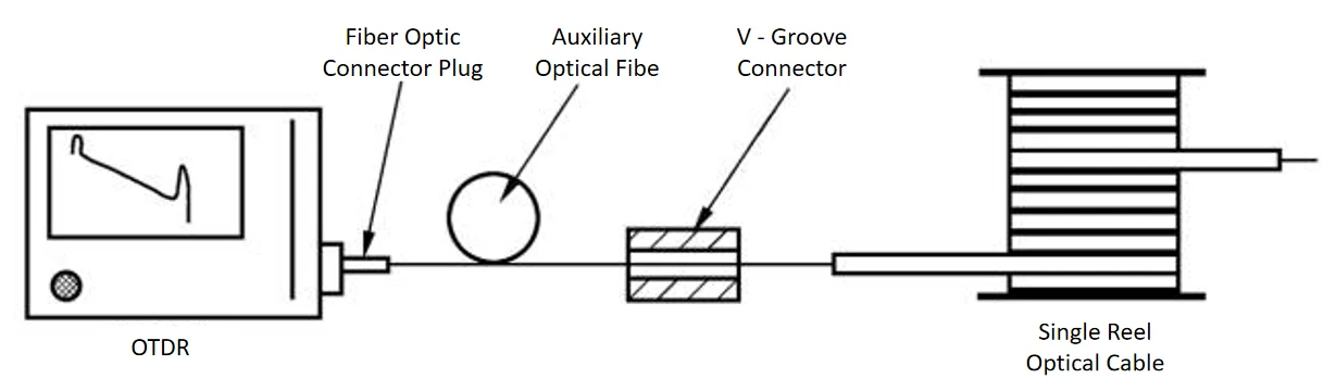
- Backscattering Method: A non-destructive method with the feature of single-ended (one-way) measurement.
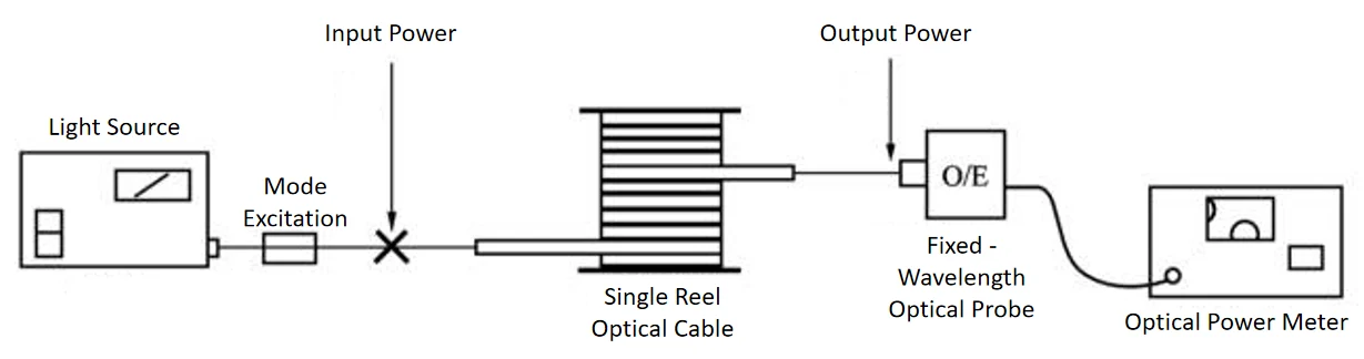
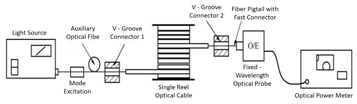
- Insertion Loss Method: Also known as the intervention loss method, it is also a non-destructive measurement method.
- Cut-Back Method: A destructive method based on N measurements.
| Method | Advantages | Disadvantages |
|---|---|---|
| Cut-Back Method | 1. Recommended by ITU-T as the benchmark method; the measurement principle conforms to the definition of loss, with high measurement accuracy.2. Low requirements for the instrument itself; measurement accuracy is less affected by the instrument. | 1. Destructive (requires cutting the cable).2. High requirements for optical injection conditions, environment, and the operator’s skills.3. Complex testing and time-consuming. |
| Backscattering Method | 1. Non-destructive.2. Features single-ended measurement.3. Can be conducted simultaneously with length re-measurement and backscattering signal curve observation, with high speed and efficiency.4. Convenient and easy to operate. | 1. High requirements for the dynamic range of the Optical Time-Domain Reflectometer (OTDR).2. Measurement accuracy is greatly affected by the instrument itself. |
| Insertion Loss Method | 1. Non-destructive.2. Low requirements for the instrument itself. | 1. High requirements for V-groove connectors.2. Not mature for single-reel measurement; only suitable for general measurement. |
3.2.2 Insulation Inspection of Cable Sheaths
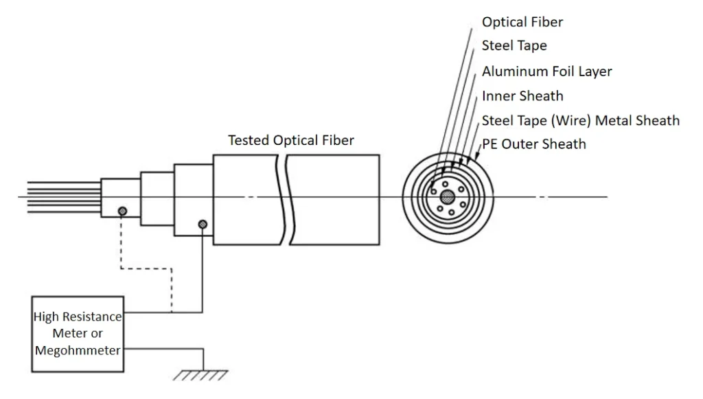
The insulation of cable sheaths is checked by measuring the ground insulation of the cable’s metal sheaths (such as longitudinal aluminum sheaths (LAP) and steel tape or steel wire armor layers) to determine whether the outer cable sheath (PE) is intact.
① Ground Insulation Measurement of Sheaths
- a. Measurement of insulation resistance.
- b. Measurement of dielectric strength.
3.2.3 Inspection of Other Materials
Including quantity counting and quality inspection of cable connection materials, fiber connectors (with pigtails), plastic conduits for ducts, cable protection materials, and unmanned repeater cabinets and their accessories.
① Inspection of Cable Joint Sleeves (Boxes) and Accessories
- a. Count the quantity.
- b. Check the quality.
Example: List of Buried/Duct Cable Joint Sleeves and Parts
| Serial No. | Name | Quantity (per set) | Remarks |
|---|---|---|---|
| 1 | Metal Main Sleeve | 1 set | – |
| (1) | Stainless Steel Sleeve | 1 piece | – |
| (2) | Outer Sealing Cover of Stainless Steel Sleeve | 2 pieces | – |
| (3) | Inner Sealing Cover of Stainless Steel Sleeve | 2×2 pieces | – |
| (4) | Large Sealing Gasket | 2 pieces | – |
| (5) | Small Sealing Gasket | 2×2 pieces | – |
| (6) | M16 Stainless Steel Bolt (Outer) | 4×2 pieces | – |
| (7) | M16 Stainless Steel Bolt (Inner) | 4×2 pieces | – |
| 2 | Splicing Metal Bracket | 1 set | – |
| 3 | Fiber Storage Box | 1 set | Includes base plate and cover plate |
| 4 | Self-Adhesive Joint Fixing Rubber Plate (inside the fiber storage box) | 1 piece | 1 piece for 6-fiber cables |
| 5 | Fiber Heat-Shrinkable Protection Tube | 10 pieces | 15 pieces for 12-fiber cables |
| 6 | Strength Member Connector & Transition Tube for Cross-Line | 1 each | – |
| 7 | Copper Wire Connector | 10 pieces | For 8 copper wires |
| 8 | Sealing Tape | 1–5 strips | – |
| 9 | Plastic Sleeve Tip | 2 pieces | – |
| 10 | Main Heat-Shrinkable Sleeve | 1 piece | Sleeved outside the joint |
| 11 | 26.5×4.5 Heat-Shrinkable Tube | 2 pieces | For cables on both sides |
| 12 | 20×3 Heat-Shrinkable Tube | 1 piece | For ground wire lead |
| 13 | Copper Lug | 1 piece | For ground wire lead |
| 14 | Desiccant | 2 packs | – |
| 15 | Cleaning Agent, Tinfoil Paper, Sandpaper | A small amount | – |
② Inspection of pipeline plastic sub-ducts and other protective pipes
- a. Inspection of plastic sub-ducts
- b. Inspection of buried optical cable protective pipes
| Compressive Strength (kg/cm²) | Tensile Strength (kg/cm²) | Elongation at Break (%) | Inner Diameter of Sub – duct Take – up Reel |
|---|---|---|---|
| ≥4 | ≥80 | ≥200 | ≥24 times the outer diameter of the sub – duct |
③ Inspection of installation equipment for unmanned stations
- a. Inspection of unmanned repeater cabinets
- b. Inspection of pigtail optical cables
④ Inspection of optical cable connectors and terminal frames (panels)
- a. Inspection of optical fiber connectors
- b. Inspection of terminal frames (panels)
- c. Inspection of connector mating
4. Route Re-Survey of Fiber Optic Cables
The route re-survey of fiber optic cable lines is the first task after the official start of the fiber optic cable line project. Based on the construction design, the re-survey involves necessary measurements and rechecks of the route to determine the specific route location for cable laying, measure the accurate ground distance, and provide necessary data for cable reel allocation, laying, and protection sections. It ensures the high-quality and on-schedule completion of the project.
4.1 Main Tasks of Re-Survey
- Verify the cable route direction, laying method, environmental conditions, and repeater station location according to the design requirements.
- Measure and verify the ground distance between relay sections; for duct routes, measure the distance between manholes.
- Verify the technical measures and sections for crossing railways, highways, rivers, canals, and other obstacles, and confirm the feasibility of implementing each specific measure in the design.
- Verify the length, measures, and implementation feasibility of the “three protections” (protection against mechanical damage, lightning, and termites) sections.
- Verify and revise the construction design drawings.
- Verify the sections, scope, and feasibility of compensation for crops and gardens; and confirm the feasibility of “detouring” in difficult sections.
- Observe the terrain and landform, and initially determine the environmental conditions of the joint locations.
- Provide necessary data and materials for cable reel allocation, cable storage, and laying.
Minimum Clearance (m) Between Direct-Buried Cables and Other Construction Facilities
| Name of Construction Facility | Minimum Clearance (m) | ||
| Parallel | Crossing | ||
| Urban Telephone Duct (Edge Line) | 0.75 | 0.25 | |
| Non-Co-Trench Buried Communication Optical/Electrical Cables | 0.5 | 0.5 | |
| Buried Power Cables | ≤35kV | 0.5 | 0.5 |
| >35kV | 2 | 0.5 | |
| Water Supply Pipes | <30cm | 0.5 | 0.5 |
| 30–50cm | 1 | 0.5 | |
| >50cm | 1.5 | 0.5 | |
| High-Pressure Oil/Gas Pipes | 10 | 0.5 | |
| Heat Pipes/Sewage Pipes | 1 | 0.5 | |
| Drainage Pipes | 0.8 | 0.5 | |
| Gas Pipes | <3kg/cm² | 1 | 0.5 |
| 3–8kg/cm² | 2 | 0.5 | |
| Building Red Line (or Foundation) | 1 | – | |
| Trees | Urban/Village Large Trees/Fruit Trees | 0.75 | – |
| Rural Large Trees | 2 | – | |
| Wells/Tombs | 3 | – | |
| Manure Pits/Compost Pits/Biogas Digesters, etc. | 3 | – | |
Note: When steel pipe protection is used, the minimum clearance for crossing water pipes, gas pipes, and oil pipes can be reduced to 0.15m.
Minimum Horizontal Clearance (m) Between Aerial Cables and Other Facilities/Trees
| Name | Minimum Clearance | Remarks |
|---|---|---|
| Fire Hydrants | 1 | – |
| Railways | 1.33H | H refers to the pole height from the ground |
| Sidewalks (Curb Stones) | 0.5 | – |
| Urban Trees | 2 | – |
| Rural Trees | 2 | – |
Minimum Vertical Clearance (m) Between Aerial Cables and Other Buildings/Trees
| Name | Parallel | Crossing | ||
| Clearance | Remarks | Clearance | Remarks | |
| Streets | 4.5 | Minimum cable height from the ground | 5.5 | Minimum cable height from the ground |
| Alleys | 4 | Minimum cable height from the ground | 5 | Minimum cable height from the ground |
| Railways | 3 | Minimum cable height from the ground | 7.5 | Minimum cable height from the ground |
| Highways | 3 | Minimum cable height from the ground | 5.5 | Minimum cable height from the ground |
| Dirt Roads | 3 | Minimum cable height from the ground | 4.5 | Minimum cable height from the ground |
| Buildings | – | – | 0.6 (to ridge) / 1.5 (to roof) | Minimum cable height from the ridge or flat roof |
| Rivers | – | – | 1.6 | Minimum cable height from the top of the highest mast at the highest water level |
| Urban Trees | – | – | 1.5 | Minimum cable height from the top of the tree branches |
| Rural Trees | – | – | 1.5 | Minimum cable height from the top of the tree branches |
| Communication Lines | – | – | 0.6 | Minimum cable of one side to the maximum cable of the other side |
4.2 Re-Survey Methods
- Composition of the Re-Survey Team: Organized by the construction unit, the team usually includes personnel from the construction, maintenance, construction, and design units. The re-survey should be conducted before cable reel allocation.
- General Re-Survey Methods:
- Route Setting: Determine the starting point, turning points, and intermediate straight poles.
- Distance Measurement: Use a 100m ground chain (50m in mountainous areas) to measure the actual ground distance.
- Marker Stake Placement: For example, a stake at 8.152km is marked as “8+152”; place counting stakes every 100m, key stakes every 1km, and marker stakes at turning points.
- Line Marking: Mark the location with white lime powder or lime.
- Mapping: Use a scale of 1:500 or 1:1000 for urban areas, 1:2000 for suburban areas; 1:500–5000 for plane maps, and 1:50–100 for cross-sectional maps.
- Registration: Record the length, location, soil quality, facilities, protection measures, and reinforcement measures.
4.3 Cable Reel Allocation
4.3.1 Purpose of Cable Reel Allocation
To use cables reasonably, reduce cable joints and joint loss, save cables, and improve the quality of fiber optic communication projects.
4.3.2 Methods of Cable Reel Allocation
- Basic Steps of Reel Allocation
- a. Prepare a summary table of the total length of the cable route.
- b. Prepare a summary table of cables.
- c. Cable Allocation Table for Each Relay Section
| Relay Section Name | |||||
| Design Total Length (km) | |||||
| Re-Surveyed Ground Length (km) | Buried | ||||
| Duct | |||||
| Aerial | |||||
| Waterway | |||||
| Slope | |||||
| Indoor (Station) | |||||
| Total | |||||
| Serial Number | Reel Number | Specification, Model | Reel Length (km) | Remarks |
| Relay Section Name | Cable Type | Quantity(km) | Factory Reel No. | Remarks | |
| Specification/Model | Planned Quantity | Actual Allocated Quantity (km) | |||
- Steps of Cable Reel Allocation for Relay Sections
- a. Determine the allocation direction.
- b. Clarify requirements for station entry cables.
- c. Calculation of Optical Cable Routing Length
- Calculate the cable laying length using the following formula:
- L = L_buried + L_duct + L_aerial + L_waterway + L_slope
- L_buried: Laying length of direct-buried cables = Surveyed length of buried section + Reserved length for buried section
- L_duct: Laying length of duct cables = Surveyed length of duct section + Reserved length for duct section
- L_aerial: Laying length of aerial cables = Surveyed length of aerial section + Reserved length for aerial section
- L_waterway: Laying length of underwater cables = (L1 + L2 + L3 + L4 + L5) × (1 + a′) (a′ is the reserved coefficient)
- Calculate the cable laying length using the following formula:
- d. Reel Allocation Method for Duct Cables
- Master the following key points:
- The surveyed ground distance of the route must be accurate and checked against the original maps of the maintenance department.
- Selecting appropriate single-reel cable lengths and joint manholes is the focus of reel allocation.
- Master the following key points:
- e. Key Points of Reel Allocation Method for Buried Cables
- The total length of general relay sections shall comply with the previous table (Cable Allocation Table for Each Relay Section).
- For relay sections with tight planned cable quantities, “fixed cable and fixed location” allocation must be adopted.
- For buried cables, “adjustment reels” should be allocated according to the cable laying conditions during reel allocation.
5. Cable Laying
To ensure the safety and success of cable laying, the following regulations must be followed:
- The bending radius of the cable shall not be less than 15 times the cable outer diameter, and not less than 20 times the cable outer diameter during construction.
- The traction force for cable laying shall not exceed 80% of the maximum allowable tension of the cable; the instantaneous maximum traction force shall not exceed the maximum allowable tension of the cable, and the main traction force shall act on the cable’s strength member.
- For cables requiring A/B end identification, lay them in the direction specified in the design.
- To prevent torsion damage to the cable during traction, a swivel shall be added between the cable traction head and the traction rope. The cable traction head can be prefabricated or made on-site.
- When laying the cable, the cable must be released from the top of the cable reel and maintained in a relaxed arc shape. No torsion shall occur during the laying process, and back loops and surges are strictly prohibited.
- For mechanical traction laying, the speed adjustment range of the traction machine shall be 0–20m/min with stepless speed regulation; the traction tension can also be adjusted, and the machine shall automatically alarm and stop traction when the traction force exceeds the specified value.
- For manual traction laying, the speed shall be uniform, generally controlled at about 10m/min, and the traction length shall not be too long; traction can be conducted in several stages.
- To ensure the quality and safety of cable laying, the construction process must be well-organized and directed by a dedicated person. Good communication means must be available. It is strictly prohibited for untrained personnel to work or operate without communication tools.
5.1 Laying of Aerial Fiber Optic Cables
Overhead pole lines boast the advantages of low investment and a short construction cycle. Therefore, the overhead installation method is widely adopted for long-distance intra-provincial trunk lines, where optical cables are attached to existing long-distance intra-provincial pole lines or part of rural and urban telephone pole lines. National inter-provincial trunk lines and urban telephone trunk lines generally do not use the overhead method; however, in scenarios such as complex terrain with impenetrable obstacles or undetermined urban planning in urban areas, inter-provincial trunk lines may also adopt partial or temporary transitional overhead installation. Nevertheless, overhead installation of long-distance trunk optical cables is not suitable in areas with overweight load, areas where the temperature is below -30℃, areas with a large number of long spans, as well as areas affected by severe sandstorms or frequent typhoons.
Overhead optical cables mainly fall into two types: steel strand-supported type and self-supporting type, among which the steel strand-supported type is recommended as the priority. The erection of steel strand-supported optical cables is further divided into two methods: suspension type and wrapping type. The wrapping type has the advantages of high construction efficiency, strong wind pressure resistance and ease of maintenance, but it is generally not recommended due to numerous restrictions on its construction conditions.
5.1.1 Pole Line and Suspension Wire
- The construction of aerial cable lines is divided into two scenarios: new cable line construction and cable erection after renovation of existing pole lines.
- The design of new lines is based on the type of cable to be erected, environmental conditions, and other safety factors.
- China classifies load zones into four categories based on three factors: wind force, ice coating, and temperature.
- For cable lines crossing small rivers or other obstacles, long-span design can be adopted.
- Generally, in light load zones, pole spans exceeding 70m; in medium load zones, pole spans exceeding 65m; and in heavy load zones, pole spans exceeding 50m are classified as long spans. In addition to the main suspension wire for hanging cables, an auxiliary suspension wire is required, which is generally a 7/3.0 steel strand.
For the overhead optical cable installation in long pole spans, it is required that the sag of the optical cable in the long pole spans after suspension should be basically consistent with that of the entire line.
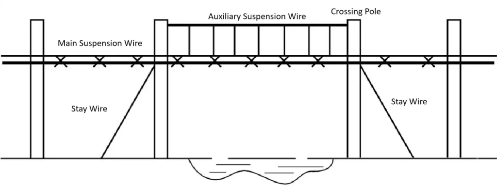
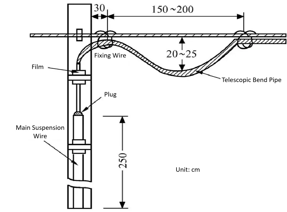
A telescopic bend should be made for the overhead optical cable at each pole to prevent fiber stress caused by thermal expansion and contraction of the optical cable. The overhead optical cable should be coiled and reserved on the electric poles at certain intervals for use in optical cable repair.
Installation methods and requirements for overhead optical cable uplead: The lower part of the pole should be protected with a steel pipe to prevent man-made damage, and a telescopic bend should be reserved at the upper hanging part to avoid the impact of climate changes.
| Load Zone | Steel Strand Type | Pole Spacing (m) | Optical Cable Weight (kg/m) |
| Light Load Zone | 7/2.2 Steel Strand | ≤45 | ≤2.1 |
| ≤60 | ≤1.5 | ||
| ≤80 | ≤1.0 | ||
| Medium Load Zone | 7/2.2 Steel Strand | ≤45 | ≤1.8 |
| ≤50 | ≤1.5 | ||
| ≤60 | ≤1.0 | ||
| Heavy Load Zone | 7/2.2 Steel Strand | ≤35 | ≤1.5 |
| ≤45 | ≤1.0 | ||
| ≤50 | ≤0.6 | ||
| Heavy Load Zone | 7/2.6 Steel Strand | ≤30 | ≤2.5 |
| ≤45 | ≤1.5 | ||
| ≤50 | ≤1.0 | ||
| Hook Type | Optical Cable Outer Diameter (mm) | ||
| 65 | Above 32 | ||
| 55 | 25 ~ 32 | ||
| 45 | 19 ~ 24 | ||
| 35 | 13 ~ 18 | ||
| 25 | Below 12 | ||
5.1.2 Erection of Suspended Cables
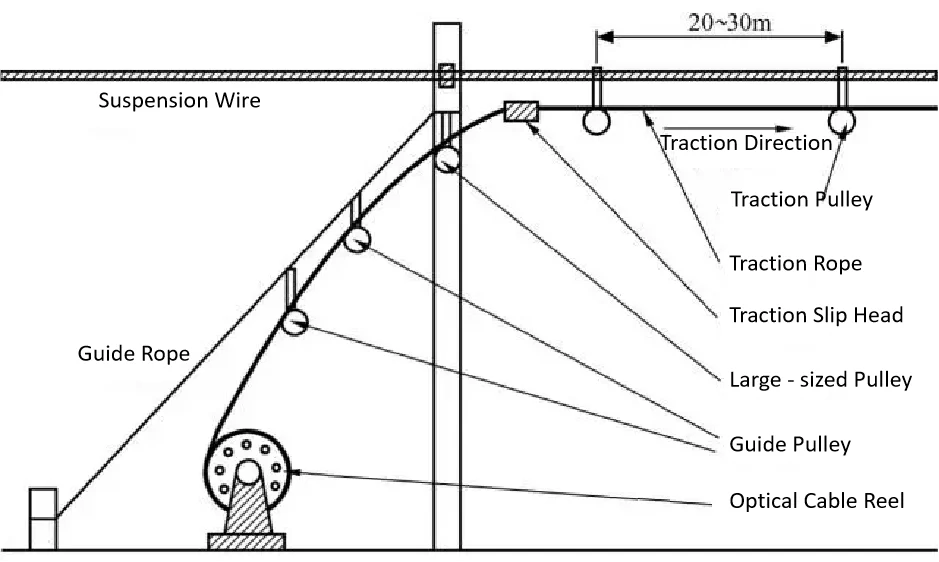
To avoid damaging the cable sheath, the pulley traction method is generally adopted:
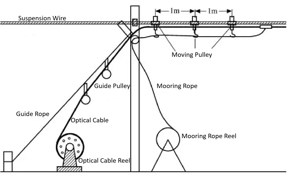
- Install guide ropes and two guide pulleys on the cable reel side (starting end) and the traction side (terminal end), respectively; install a large pulley (or tension pulley) at the appropriate position on the utility pole. Then install a guide pulley every 20–30m on the suspension wire (it is better for the installer to operate while sitting on a pulley block). After installing each pulley, thread the traction rope into the pulley. Use manual labor or a traction machine to pull at the end (pay attention to tension control).
- After the cable traction is completed, start from one end and use cable hooks to hang the cable on the suspension wire, then remove the guide pulleys. The hook spacing is (50±3)cm, and the first hook on both sides of the utility pole is about 25cm from the fixed point of the suspension wire on the pole. The hook type shall be consistent, and the buckle direction shall be consistent.
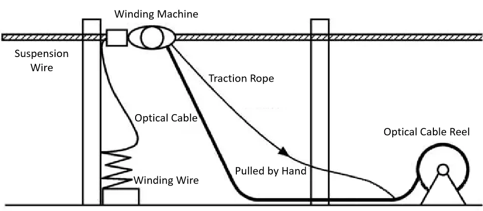
5.1.3 Winding-type Erection
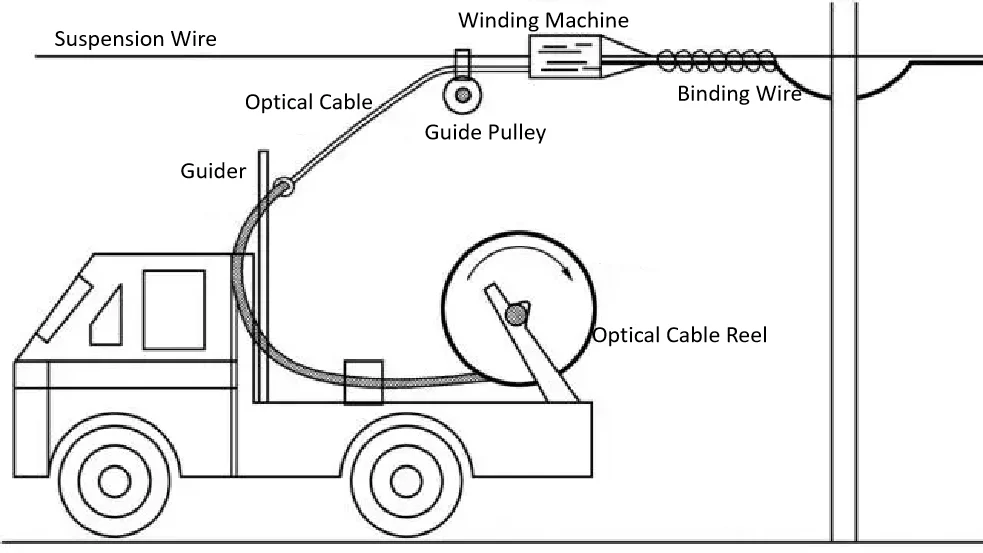
- The successful development of new small automatic winding machines makes the winding method erection both of good quality and labor-saving and time-saving, becoming a relatively ideal erection method. The optical cable reel is supported by a hydraulic jack bracket at the rear of the truck. The truck moves forward slowly, and the optical cable is sent out through the delivery hose and the guide. At the same time, the traction wire fixed on the guide pulls the winding machine to move with the truck.
- The winding machine is divided into two parts: rotatable and non-rotatable. The non-rotatable part is driven by the traction wire to move along the optical cable, and a friction roller drives the binding wire box to rotate around the suspension wire and the optical cable, realizing the laying of the optical cable. Winding and binding are completed automatically at one time.
- When the optical cable is laid to the electric pole, the operator is sent up by using the lifting seat of the truck to complete the telescopic bend on the pole, fix the binding wire, and move the optical cable winding machine over the pole for installation. This construction method saves labor, time and effort, and has high erection efficiency, but it is only limited to the line pavement where trucks can travel.
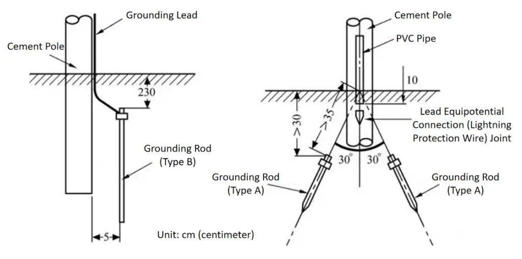
5.1.4 Grounding Protection of Overhead Optical Cable
To protect the overhead line equipment and the safety of maintenance personnel, the metal sheath of the overhead optical cable and the steel suspension wire of the optical cable should be grounded.
The following table lists the grounding resistance values of linear grounding bodies with different lengths in different soils
| Soil resistivity | resistance (Ω) of Φ4mm steel wire buried at a depth of 0.6m for the following lengths | resistance (Ω) of Φ4mm steel wire buried at a depth of 1.0m for the following lengths | |||||||||
| 1m | 2m | 3m | 4m | 5m | 6m | 1m | 2m | 3m | 4m | 5m | |
| 20 | 19 | 12 | 9 | 7 | 6 | – | 17 | 11 | 8 | 6.5 | 6.5 |
| 50 | 47.5 | 29.5 | 22 | 17.5 | 14.5 | – | 43 | 27.5 | 21 | 17 | 14 |
| 60 | 57 | 35.5 | 26 | 21 | 17.5 | – | 52 | 33 | 25 | 20 | 17 |
| 80 | 76 | 47 | 35 | 28 | 23.5 | – | 69 | 44 | 33 | 28 | 22 |
| 200 | 177 | 131 | 105 | 88 | 158 | – | 165 | 123 | 99 | 84 | 76 |
| 485 | 180 | 236 | 174 | 140 | 117 | – | 145 | 220 | 164 | 132 | 110 |
| 440 | 418 | 260 | 182 | 154 | 129 | – | 379 | 142 | 180 | 145 | 123 |
| Soil Resistivity (Ω·m) | ≤100 | 100 – 300 | 301 – 500 | ≥501 |
| Soil Properties | Black Soil, Peat, Loess, Sandy Clay | Sandy Soil Intercalated With Sand | Sandy Soil | Stony Soil |
| Grounding Resistance (Ω) | – | – | – | – |
| General Pole Lightning Protection Grounding | ≤80 | ≤100 | ≤150 | ≤200 |
| Terminal Pole, H-pole | – | ≤10 | – | – |
| Poles On Both Sides At The Intersection With High-voltage Power Lines | – | ≤25 | – | – |
5.2 Laying of Duct Fiber Optic Cables
Key Words: Duct Material, Parallel Clearance, Crossing Clearance, Burial Depth, Section Length, Thickness, Reserved Cable, Height Difference
5.2.1 Laying Methods of Duct Optical Cable
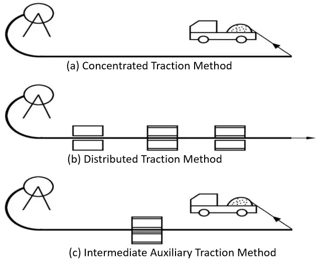
(1) Mechanical Traction Method: ① Centralized Traction Method; ② Distributed Traction Method; ③ Intermediate Auxiliary Traction Method
(2) Manual Traction Method: 1–2 personnel shall be assigned in each manhole to assist with pulling; generally, the traction force of one person when pulling by hand is 30 kg. A commonly used method is the “frog jump” laying method, i.e., laying the cable in an “∞” (infinity) shape.
(3) Combined Laying Method (Mechanical + Manual): This method is quite in line with China’s national conditions. ① The intermediate manual auxiliary traction mode accelerates the laying speed, makes full use of on-site labor, and improves work efficiency. ② The terminal manual auxiliary traction mode extends the length of one-time traction, reduces the number of “frog jumps” required in the manual traction method, and increases the laying speed.
5.2.2 Laying Procedures of Duct Optical Cable
(1) Estimate traction tension and formulate laying plan: ① Route survey and investigation; ② Formulate optical cable laying plan
(2) Pull in steel wire rope: Generally, iron wire or nylon rope is used.
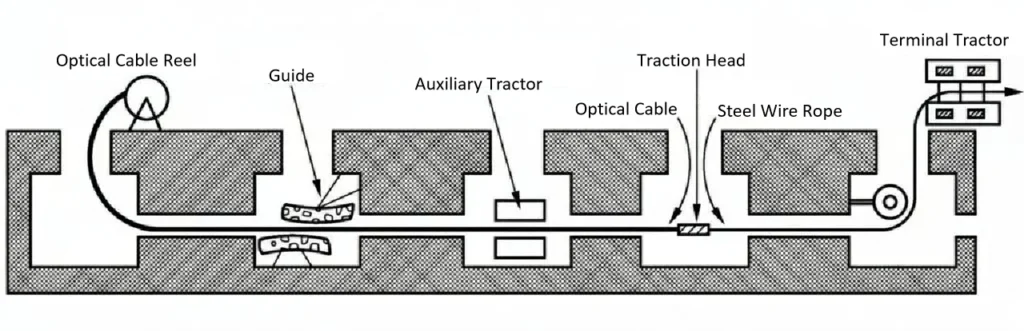
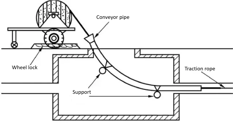
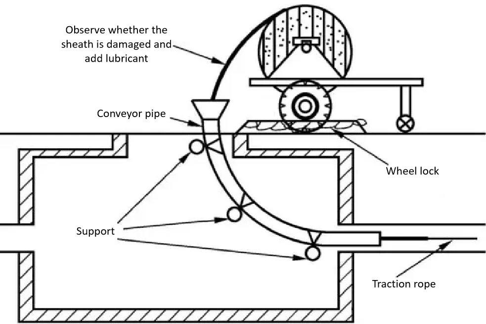
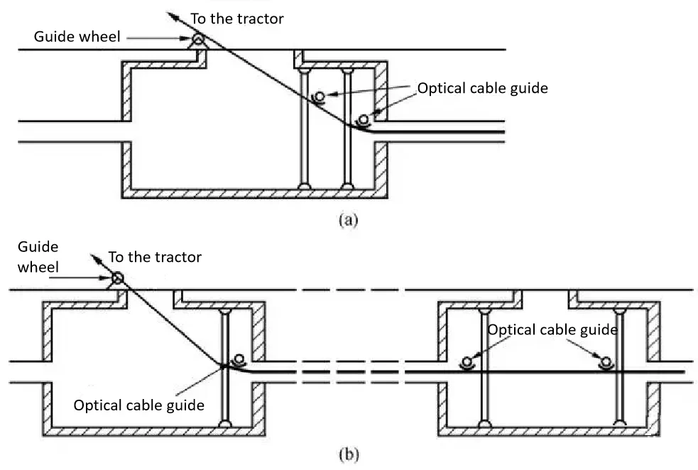
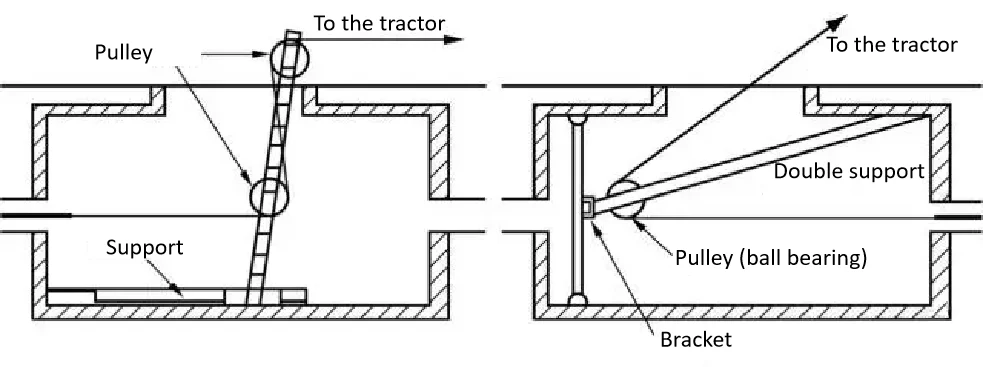
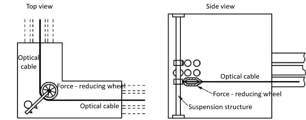
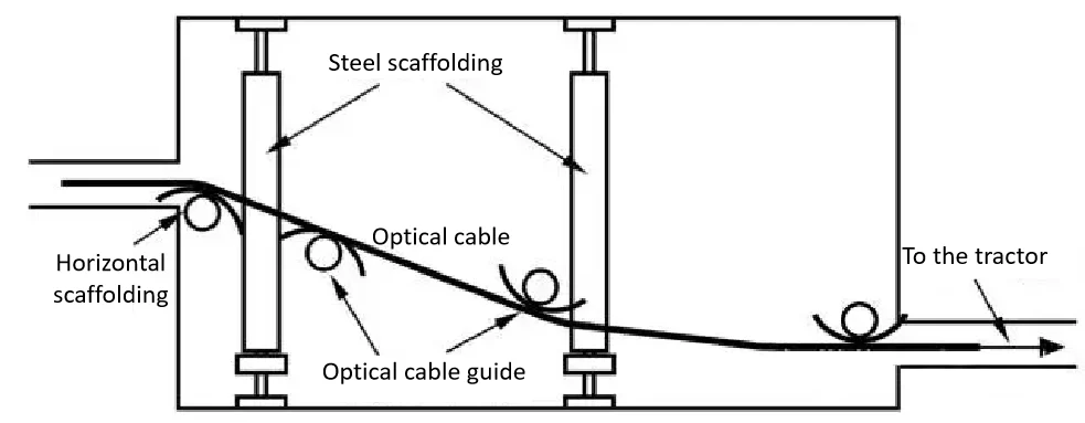
(3) Installation of optical cable and traction equipment: ① Placement of optical cable reel and installation of cable inlet; ② Installation at the optical cable outlet; ③ Installation of force-reducing device at bends; ④ Installation of guide for height difference of pipe holes; ⑤ Preparation work for intermediate traction
(4) Optical cable traction: ① Fabricate the end of the optical cable and connect it to the steel wire rope; ② Start the terminal traction machine in accordance with the requirements for traction tension and speed; ③ After the optical cable is pulled to the position of the auxiliary traction machine, install the optical cable properly, and operate the auxiliary machine at the same speed as the terminal traction machine; ④ Reserve sufficient length for splicing and testing; if more optical cables need to be led out of the manhole, special attention must be paid to the lateral pressure at the inner guide pulley of the manhole outlet and the friction point on the manhole wall to avoid compression deformation of the optical cable.
Note: Smooth communication must be maintained during laying for emergency use.
5.2.3 Installation of Optical Cable in Manholes
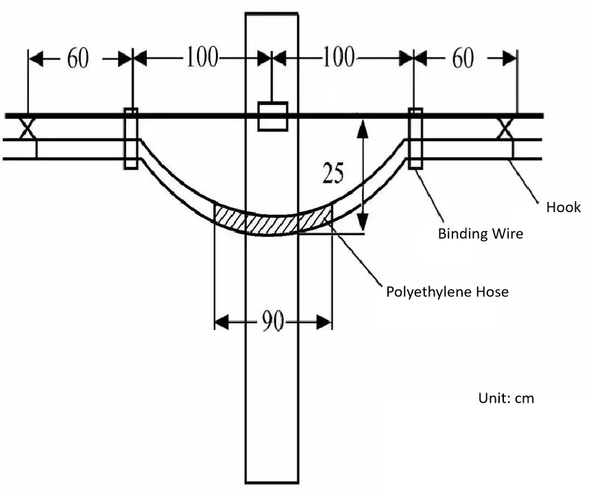
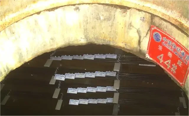
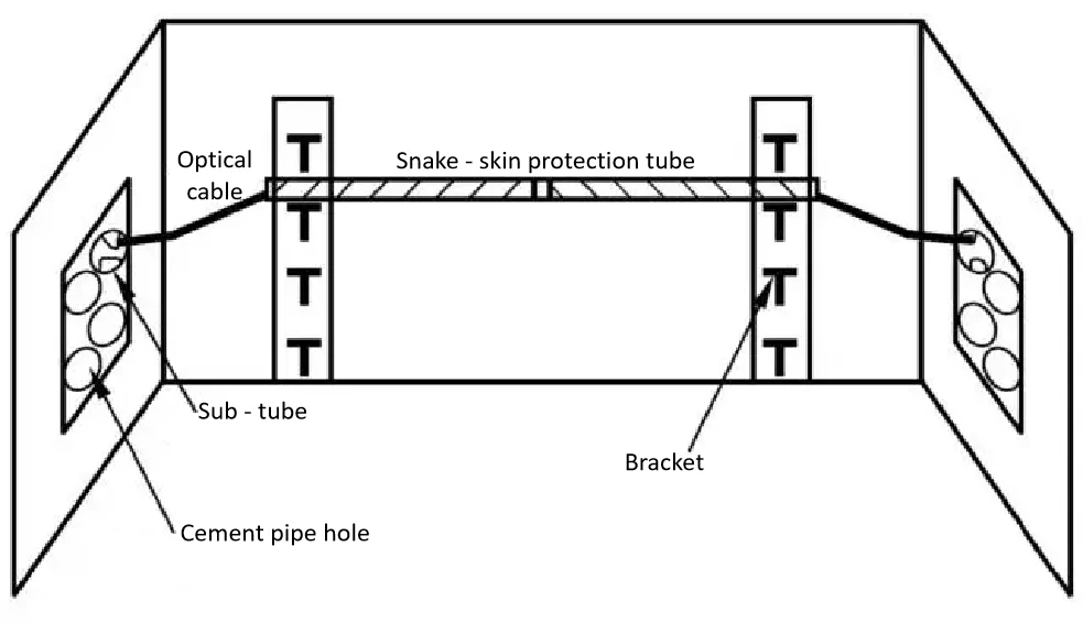
(1) Fixation and Protection of Optical Cable in Straight-through ManholesAfter the optical cable is pulled in, the surplus cable in each manhole shall be manually placed on the specified bracket along the manhole wall, and it is generally placed on the upper layer as far as possible. For the future safety of the optical cable, a snake-skin hose or PE hose is usually used for protection, and the cable is fixed with binding wire.
(2) Fixation of Surplus Optical Cable for Splicing in ManholesThe reserved length of the optical cable for splicing in the manhole is generally not less than 8 meters. Since the splicing work often takes several days or even longer, the surplus optical cable shall be properly coiled and stored in the manhole. The specific requirements are as follows: ① Seal the end of the optical cable properly: To prevent water from entering the end of the optical cable, a heat-shrinkable cap shall be used for heat-shrink treatment on the cable end. ② Coil and fix the surplus cable: The surplus optical cable shall be coiled according to the bending requirements, then hung on the manhole wall or tied to the inner cover of the manhole. Note that the cable end must not be immersed in water.
5.2.4 Installation of Optical Cable in Manholes
(1) Fixation and Protection of Optical Cable in Straight-through ManholesAfter the optical cable is pulled in, the surplus cable in each manhole shall be manually placed on the specified bracket along the manhole wall, and it is generally placed on the upper layer as far as possible. For the future safety of the optical cable, a snake-skin hose or PE hose is usually used for protection, and the cable is fixed with binding wire.
(2) Fixation of Surplus Optical Cable for Splicing in ManholesThe reserved length of the optical cable for splicing in the manhole is generally not less than 8 meters. Since the splicing work often takes several days or even longer, the surplus optical cable shall be properly coiled and stored in the manhole. The specific requirements are as follows: ① Seal the end of the optical cable properly: To prevent water from entering the end of the optical cable, a heat-shrinkable cap shall be used for heat-shrink treatment on the cable end. ② Coil and fix the surplus cable: The surplus optical cable shall be coiled according to the bending requirements, then hung on the manhole wall or tied to the inner cover of the manhole. Note that the cable end must not be immersed in water.
5.2.5 “High-Pressure Airflow Propulsion Method” for Silicone-Core Tube Conduits and Optical Cables
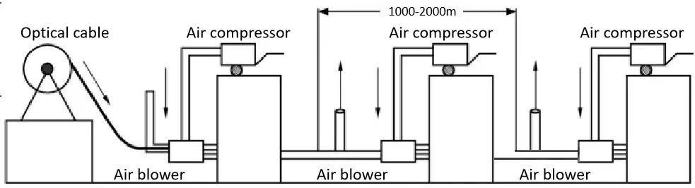
Referred to as the air-blowing method for short, it uses a slight mechanical thrust generated by an optical cable injector and high-speed, high-pressure airflow flowing over the surface of the optical cable to keep the optical cable in a suspended state inside the plastic tube and drive it forward, thereby reducing friction damage to the optical cable in the conduit.
This method is easy to operate and allows for a long air-blowing distance. Moreover, due to the presence of a safety protection device, it will automatically stop if the cable encounters excessive resistance during advancement, so it will not cause any damage to the cable. It is an excellent laying method.
Under normal circumstances, a single air blower can blow a length of 1,000 to 2,000 meters at one time. The restrictive factors mainly include terrain, the ratio of the inner diameter of the conduit to the outer diameter of the optical cable, the mass per unit length of the optical cable, materials, and the ambient temperature and humidity during construction. If multiple air blowers are used for continuous air-blowing, the reel length of the optical cable can be 4km or 6km.
On expressways, a handhole is generally set every 1km, serving as an air-blowing point and a branch processing point for emergency phones, monitoring, etc. A manhole is set at each optical cable splicing point (every 2km or 4km).
When laying a small number of silicone tubes in easily excavated areas in the field (such as in communication trunk line projects), as long as a sealed interface is added at the optical cable splicing point, it can be used as an air-blowing point or a continuous air-blowing point. After the cable is threaded, the interface is tightened, and the conduit remains in a closed and integrated state.
① Characteristics, Physical Properties and Technical Parameters of Silicone-Core Tubes
a Main characteristics: High-density polyethylene (HDPE) silicone-core tubes are currently the most widely used and advanced protective sleeves for communication optical cables. They are made by co-extrusion of special HDPE raw materials and silicone materials.
b Specifications and reel lengths: There are two main specifications of HDPE silicone-core tubes commonly used in the construction of optical cable conduits—40/33mm and 46/38mm, with reel lengths of 2000m and 1500m respectively.
| Nominal Diameter /mm | Outer Diameter /mm | Outer Diameter Tolerance /mm | Minimum Inner Diameter /mm | Wall Thickness /mm | Wall Thickness Tolerance /mm | Reel Length /m |
| 32/26 | 32 | 0-0.3 | 26 | 3 | ±0.15 | 3000+9 |
| 32/28 | 32 | 0-0.3 | 28 | 2 | ±0.15 | 3000+9 |
| 40/33 | 40 | 0-0.3 | 33 | 3.5 | ±0.20 | 2000+9 |
| 46/38 | 46 | 0-0.3 | 38 | 4 | ±0.20 | 1500+5 |
| 50/42 | 50 | 0-0.4 | 42 | 4 | ±0.20 | 1200+4 |
| 60/52 | 60 | 0-0.5 | 52 | 4 | ±0.25 | 700+3 |
② Installation of Silicone-Core Tube Conduits
a Basic Requirements for Installation: The trench bottom shall be flat; sharp bends are prohibited; and height differences shall be gradual.
b Connector Tools
- Air-Tight Interface: Made of special PE material.
- Repair Tube: Made of special PE material.
- Cable-Resistant Plug
- Cable Protection PlugSpecial tools for silicone-core tube installation include silicone-core tube cutters, interface wrenches, pulley cutters, and repair pliers.
c Conduit Installation Method: After transporting the conduits to the burial location at the construction site, use special tools to set up the conduit reel, level the reel shaft, and make it perpendicular to the conduit laying direction.
d Handling of Special Sections
e Installation of Handholes
③ Optical Cable Installation in Silicone-Core Tube Conduits – Air-Blowing Method
5.3 Laying of Direct-Buried Fiber Optic Cables
5.3.1 Trench Digging
| Laying Section and Soil Type | Burial Depth (m) | Remarks |
|---|---|---|
| Ordinary Soil (Hard Soil) | ≥1.2 | – |
| Semi-Rocky (Sandy Soil, Weathered Rock) | ≥1.0 | – |
| Full Rock | ≥0.8 | Calculated from the top of the 10cm-thick fine soil or sandy soil padding |
| Quicksand | ≥0.8 | – |
| Suburban and Rural Areas | ≥1.2 | – |
| Urban Sidewalks | ≥1.0 | – |
| Crossing Railways and Highways | ≥1.2 | Calculated from the bottom of the track bed or the road surface |
| Ditches, Canals, and Ponds | ≥1.2 | – |
| Farmland Drainage Ditches (Width ≤1m) | ≥0.8 | – |
- The cross-sectional size of the cable trench: generally, 30–40cm for the bottom width for 1–2 cables; 55cm for 3 cables; 65cm for 4 cables. The top width of the trench is approximately the bottom width plus 0.1 times the burial depth.
- Cables laid in the same trench shall not cross or overlap.
- The depth of the cable trench at the trench embankment shall meet the requirements.
- The cable trench in two straight sections shall be as straight as possible. If there is an obstacle in the straight line, it can be detoured, but the original straight line shall be restored after detouring the obstacle. The bending radius of the turning section shall not be less than 20m.
- When the cable trench encounters existing underground structures, excavation must be carried out carefully to protect them.
5.3.2 Trench Bottom Treatment
- For general sections: Fill the trench bottom with fine soil or sand-gravel, and after tamping, its thickness shall be approximately 10 cm.
- For weathered rock and gravel sections: First lay a 5 cm-thick mixture of cement and sand in a 1:4 ratio (mortar); then fill with fine stones or sand-gravel to ensure the optical cable is not damaged by the sharp edges of gravel.
- If the outer sheath of the optical cable is steel-armored, the mortar laying can be omitted.
- For sections with soft soil that is prone to collapse, wooden piles and wooden blocks can be used as temporary retaining walls for protection.
5.3.3 Optical Cable Routing
- When laying optical cables directly along highways, mechanical routing shall be adopted. If conditions permit, the cable can be directly placed on the ground pulleys in the trench; it is forbidden to throw the optical cable from motor vehicles. Approximately every 20 meters of cable released, it shall then be manually placed into the trench.
- There are two methods of manual routing:
- Shoulder-carrying along a straight line: (Note: Regardless of the routing method, dragging the optical cable on the ground is strictly prohibited.) The spacing between personnel shall be small, and all actions shall be coordinated under the unified command of the supervisor.
- Manual lifting and placing: First, coil the optical cable into an “∞” shape. For every 2km of optical cable, stack it into 8–10 “∞” coils. Each coil shall be bound with leather threads at 5–6 points (except the first coil to be placed). Each group of 4 personnel shall lift one coil, with one coordinator assigned between adjacent groups. The front of the first group shall be guided (pulled) by 2–3 personnel, and 3–5 personnel shall be responsible for command and communication between the front and rear teams, totaling 60–65 personnel. During routing, all groups shall lift the coils under unified command, move forward along the trench, and unfold the “∞” coils one by one for placement. This method is characterized by safety, fewer personnel requirements, and time efficiency, but its disadvantage is that it cannot cross obstacles. (Referred to as the “frog-leaping method”.)
- After the optical cable is routed, designated personnel shall organize the cable from the end towards the starting point to prevent the cable from arching or twisting in the trench, eliminate potential collapses, and ensure the cable lies flat at the bottom of the trench.
5.3.4 Backfilling
- Before backfilling, the routed optical cable must be inspected and measured. Conduct a visual inspection to check for damage to the cable’s outer sheath; if damaged, repair it promptly. For optical cables with a metal sheath, perform a ground insulation resistance test, typically using a megohmmeter. For optical fibers, conduct a light transmission test or an OTDR (Optical Time-Domain Reflectometer) backscatter test.
- Only after confirming the optical cable is undamaged can backfilling begin. First, backfill with 15cm-thick fine soil or sand-gravel; strictly prohibit pushing stones, bricks, or frozen soil into the trench. During backfilling, assign personnel to step on the cable in the trench to prevent the backfilled soil from causing the cable to arch. If there is standing water in the trench, use a wooden fork to press the cable to the bottom of the trench before backfilling to avoid the cable floating. After filling the first layer of fine soil, it shall be manually tamped flat before further backfilling; tamp the soil flat every 30cm of backfill depth. The backfilled soil shall be 10cm higher than the ground surface.
- If the optical cable splice is not to be connected temporarily, the overlapping part of the cable ends must be protected with concrete slabs, bricks, etc., and marked with a clear sign until the actual splicing is completed and the protection is removed.
5.3.5 Protection for Special Sections
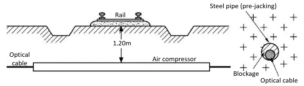
(1) When crossing railways or highways where excavation is not permitted, the pipe-jacking method shall be adopted. The jacking pipe shall be temporarily blocked before cable routing, and after routing, it shall be sealed with hemp fiber soaked in oil. The protective steel pipe shall extend 0.5–1m beyond the road trench. In areas where excavation is allowed, the direct burial method shall be used, with additional direct burial protection measures.
(2) When the cable route passes through machine-plowed roads, rural roads, urban areas, or sections prone to soil disturbance, protective measures such as laying hard plastic sheets, red bricks, or cement cover plates shall be adopted.
(3) When the optical cable crosses ditches requiring dredging or ponds/lakes where mud is dredged for fertilizer or lotus roots are planted, in addition to meeting the required burial depth, cement plates or cement sandbags shall be laid over the cable for protection.
(4) When the optical cable passes through sand rivers severely eroded by flash floods during the flood season, protective measures such as manual armoring of the cable or constructing submerged slopes with masonry shall be adopted.
(5) When the optical cable crosses ditches, ridges, or terraced fields with a height difference of over 1m, stone masonry slope protection shall be built, with joints pointed using cement mortar. For height differences between 0.8–1m, slope protection made of “3:7 soil” (a mixture of 3 parts lime and 7 parts soil) can be used. For height differences less than 0.8m, slope protection is not required, but multiple layers of tamping shall be performed.
(6) When the optical cable is laid on slopes prone to flood scouring, stone masonry plugs shall be constructed at both ends of the cable trench.
(7) When the optical cable passes through termite-infested areas, termite-resistant optical cables with a nylon outer sheath shall be selected, and toxic soil treatment shall be carried out.
5.3.6 Installation of Optical Cable Route Markers
- The function of optical cable route markers is to mark the direction of the optical cable route and the specific location of line facilities, facilitating daily maintenance and fault inspection by the maintenance department.
- Locations Where Markers Must Be Installed:
- (1) Optical cable splice points;
- (2) Optical cable turning points;
- (3) Start and end points of optical cables laid in the same trench;
- (4) Start and end points of lightning protection ground wires laid;
- (5) Locations where optical cables are reserved as per planning;
- (6) Crossing points with other important pipelines/cables;
- (7) Locations where it is difficult to locate the optical cable when crossing obstacles;
- (8) Straight-line route sections where the distance exceeds 200m (or 250m in suburban and wild areas) and locating the optical cable is difficult.
- If there are usable existing markers, they can be used instead of dedicated route markers.
- For splice points requiring monitoring of the insulation resistance of the optical cable’s metal inner sheath, monitoring markers shall be installed; all other locations shall use standard markers.
5.3.7 Requirements for Marker Installation
(1) Markers shall be buried directly above the optical cable:
- Markers for straight-line routes: Buried directly above the optical cable.
- Markers for splice points: Buried along the optical cable route, with the side of the marker bearing characters facing the optical cable splice.
- Markers for turning points: Buried at the intersection point of the route turn, with the side of the marker bearing characters facing the direction of the smaller turning angle of the optical cable. When the optical cable is laid along a highway with a spacing of no more than 100m, the markers can face the highway.
(2) Monitoring markers shall have a removable metal top cap, inside which a terminal block for connecting monitoring wires and ground wires is installed.
(3) Marker numbers shall be painted in regular script with red (or black) paint on a white background; the characters shall be neat, with a clean and clear surface. Numbering shall be conducted independently for each relay section, arranged in the direction from Terminal A to Terminal B.
5.4 Underwater Optical Cables
5.4.1 Installation Conditions for Underwater Optical Cables
(1) For rivers and lakes with stable riverbeds, low flow velocity, and narrow water surfaces, fine steel-armored underwater optical cables shall be used. This is the most widely used type in long-distance optical cable line projects at present.(2) For waterways with unstable riverbeds, excessively high flow velocity (>3 m/s), river width exceeding 150 m, or heavy traffic of water transport vehicles such as motor ships and sailboats, heavy steel-armored underwater optical cables shall be used.(3) For rivers, waters, or coastal areas where the riverbed is unstable, scouring is severe, flow velocity is high, or the riverbed is rocky (which may cause severe impact and wear to the optical cable, endangering it), double steel-armored underwater optical cables shall be preferably used.(4) For rivers with a perennial water depth exceeding 10 m, deep-water optical cables (specifically double-armored lead-sheathed deep-water optical cables) shall be adopted. These cables are relatively heavy and can sink to the riverbed, enhancing their stability and safety underwater.(5) For small rivers and ditches, ordinary direct-buried optical cables can be used, laid with cross-river plastic pipes.
- For large-scale key projects involving crossing major rivers, a backup underwater optical cable shall generally be installed. Its length and transmission characteristics shall be roughly the same as those of the main optical cable. To prevent twisting between the main and backup optical cables underwater, the distance between their deployment positions shall be at least 50–70 m.
There are two switching methods for the main and backup optical cables:
- One is the direct connection method: The main optical cable is directly connected to the onshore optical cable, while the end of the backup optical cable is stripped and prepared for splicing (to be used when needed).
- The other is the flexible connection method: Both the main and backup optical cables are connected to the pigtails of flexible connectors in a switching device (commonly known as an underwater cable “switch” box), and then switching between them and the onshore optical cable is implemented through connection coupling. This switching method has a short switching time; however, due to the use of two flexible joints and four fixed joints, the total loss will increase by approximately 2 dB.
| River Bank Conditions | Burial Depth Requirements (m) |
|---|---|
| Beach Section | 1.5 |
| Waters with Water Depth Less Than 8m (Annual Low Water Level) 1. Unstable riverbed, soft soil; 2. Stable riverbed, hard soil. | 1.5 1.2 |
| Waters with Water Depth Greater Than 8m (Annual Low Water Level) | Natural Burial |
| Waters with Dredging Plans | 1m Below the Planned Depth |
| Areas with Severe Scouring and Extremely Unstable Conditions | Below the Variation Range |
| Rocky and Weathered Rocky Riverbeds | >0.5 |
| Excavation Method | Applicable Conditions |
|---|---|
| Manual Direct Excavation | Water depth less than 0.5m, low flow velocity, and riverbed composed of clay, sandy soil, or sand. |
| Manual Interception Excavation | Water depth less than 2m, river width less than 30m, and riverbed composed of clay, sandy soil, or sand. |
| Water Pump Flushing Trench | Water depth greater than 2m and less than 8m, flow velocity less than 0.8m/s, and riverbed composed of clay or silt sand. |
| Dredger, Suction Dredge | Water depth of 8 – 12m, and riverbed composed of clay, silt, sandy soil, or small gravel. |
| Blasting | Rocky riverbed. |
| Flusher | Riverbed composed of sandy soil, sand, or coarse-fine sand. |
| Excavating and Flushing Machine | Riverbed composed of sandy soil, sand, coarse-fine sand, or hard soil. |
5.4.2 Underwater Cable Markers
When laying underwater optical cables in navigable rivers, a no-anchoring zone must be designated in the vicinity of the cables, and signboards shall be installed on the embankments on both sides of this zone. Since underwater optical cables are lighter than underwater power cables, they have a larger movable range underwater after installation; therefore, the no-anchoring zone for underwater optical cables is relatively larger.
Underwater cable signboards include triangular signboards, large square signboards, and neon light signboards. The type of signboard to be used shall be determined based on the width of the river surface and the number of passing ships. For details on the signboards, please refer to the relevant standards.
5.5 Installation of Indoor Station Optical Cables
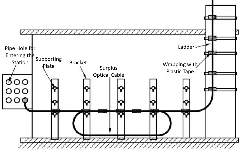
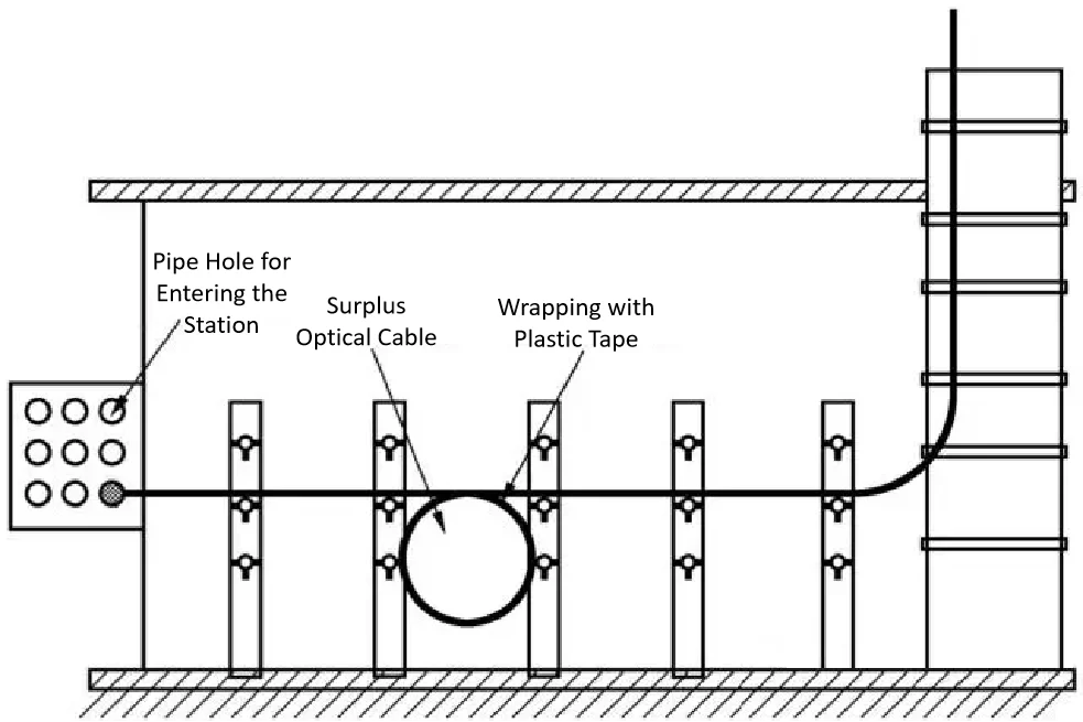
5.5.1 Routing of Indoor Station Optical Cables
- Regardless of the installation method used for outdoor optical cables, they generally enter the indoor underground cable entry room through the outdoor manhole. For most projects, ordinary outdoor optical cables are used as indoor station optical cables; for projects with special requirements, the cables shall be re-spliced into flame-retardant optical cables with a polyvinyl chloride (PVC) outer sheath in the underground cable entry room.
- Indoor station optical cables run from the underground cable entry room, along the optical (electrical) cable runway of the equipment room via a ladder, to the ODF (Optical Distribution Frame) or terminal box for termination. From the optical terminal equipment onward, indoor single-core or ribbon-type multi-core flexible optical cables shall be used instead.
- In areas severely affected by lightning strikes, the outdoor optical cables shall be terminated in the underground cable entry room. Their metal armor layers shall be connected to protection points, and all metal wires shall be connected via dedicated indoor station optical cables (which contain no metal components) and then routed to the remote power supply frame in the equipment room.
- Routing of indoor station optical cables generally can only be done manually. During routing, dedicated personnel shall be assigned at the top and bottom of ladders and each turning point to pull the cable under unified command. The cable shall be kept in a slack state during pulling; forming small loops or sharp bends is strictly prohibited.
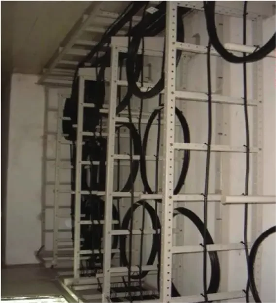
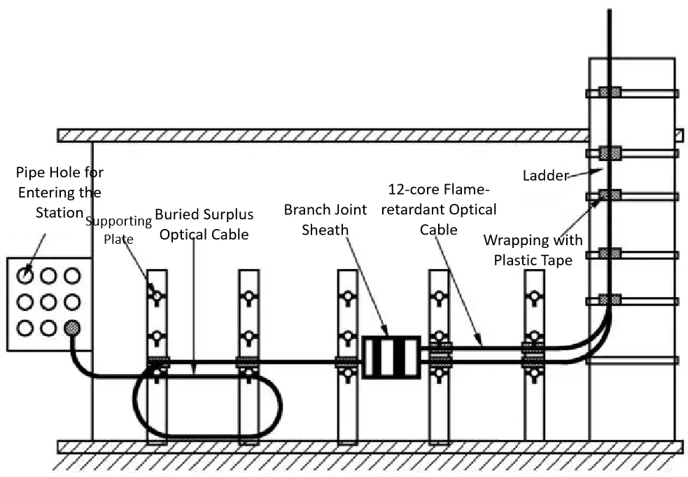
5.5.2 Installation and Securing of Indoor Station Optical Cables
- When installing and securing indoor station optical cables on ladders in the cable entry room, ordinary optical cables and flame-retardant optical cables shall be separated at the splice closure.
- For small stations without ladders, brackets shall be installed on the wall to secure the cables with ties; the cables are not allowed to hang freely over long spans.
- After entering the equipment room, indoor station optical cables in large equipment rooms are generally routed in cable trays. Care shall be taken to lay them neatly along the edge in a slack and flat manner, avoiding overlapping and crossing. At the turning points of the cable trays, appropriate 绑扎 (securing with ties) may be done. For small equipment rooms without underfloor cable troughs, the surplus cable shall be coiled into loops and fixed on the wall.
- The indoor routing of optical cables shall be neat and tidy. It is necessary to ensure the cables remain in a slack state and have a sufficient bending radius. Even if the cables are not immediately spliced and terminated after routing, they shall be temporarily secured—this is still to prevent mechanical damage to the cables or fiber breakage caused by stretching or bending of the cables.
6 Splicing and Installation of Optical Cables
6.1 Requirements for Splicing
(1) Before splicing the optical cable, verify that the type and end identification of the cable are correct; the cable shall be in good condition; the optical fiber transmission performance shall be good, and the sheath-to-ground insulation shall be up to standard (if not, identify the cause and take necessary measures to address it).
(2) Permanent marks shall be made for the optical fiber numbering inside the splice closure; when cables from two directions enter from the same side of the splice closure, unified permanent marks shall be made for the cable end identification.
(3) The method and process standards for optical cable splicing shall comply with the construction specifications and the technical requirements of different splice closures.
(4) For optical cable splicing, a good working environment shall be created. Operations shall generally be carried out in a vehicle or a splice tent to prevent dust interference; outdoor operations shall be avoided during rainy or snowy weather. When the ambient temperature is below 0°C, heating measures shall be taken to ensure the flexibility of the optical fibers, the normal operation of the fusion splicing equipment, and the normal operation of construction personnel.
(5) Sufficient slack shall be reserved for the optical cable at the splice joint and for the optical fibers inside the splice closure. The reserved length of the optical cable shall generally be no less than 4 meters, and the final reserved length of fibers inside the splice closure shall be no less than 60 centimeters.
(6) Attention shall be paid to continuous operation during optical cable splicing. For optical cable splices that cannot be completed on the same day due to unavoidable conditions, measures shall be taken to prevent moisture intrusion and ensure safety.
(7) The splice loss of optical fiber joints shall be lower than the internal control index, and the average splice loss of each optical fiber channel shall meet the requirements specified in the design documents.
6.2 Procedures and Methods for Optical Cable Splicing
The optical cable splicing procedure involves several sequential steps. First, preparations are made in terms of technology, tools, and the optical cable itself. Then, the splicing position is determined. Next, the optical cable sheath is stripped and processed. After that, splicing treatment is carried out for components like the strength member and metal sheath. Subsequently, the optical fibers are spliced. Following this, the monitoring and evaluation of optical fiber connection loss are conducted. Then, the remaining length of the optical fibers is properly accommodated. Afterward, the optical cable joint sheath is sealed (encapsulated). Finally, the optical cable joint is installed and fixed.
7 Protection of Optical Cable Communication Lines
7.1 Protection of Directly Buried Optical Cables
7.1.1 Mechanical Protection – This refers to protecting optical cables from damage caused by external forces.
When an optical cable route crosses machine-plowed fields, rural roads, urban areas, residential districts, or zones prone to soil disturbance, protective measures shall be taken in accordance with design requirements.
When the optical cable route crosses sections where excavation is not permitted (such as railways, highways, and streets), the pipe-jacking method shall be adopted, and the cable shall be protected with steel pipes or plastic pipes. Typically, this protective measure is implemented before cable routing. During cable pulling, a semi-rigid plastic pipe shall first be threaded through the steel pipe, followed by the optical cable; additionally, the pipe openings shall be sealed with hemp fiber or other materials.
For protection when crossing simple highways or rural roads, protective measures such as covering the top of the optical cable with cement cover plates or laying red bricks are generally adopted. When using bricks for protection, a 20cm-thick layer of crushed soil shall first be laid over the optical cable, after which red bricks are laid vertically. If two optical cables are laid in the same trench, red bricks shall be laid horizontally for protection.
7.1.2 Rodent and Termite Prevention Measures
(1) Measures to Prevent Termite Infestation
Termites not only gnaw on optical cables but also secrete formic acid, which accelerates the corrosion of metal sheaths.
① Based on the ecological habits of termites, when laying optical cable routes, areas with high termite infestation shall be avoided as much as possible, such as forests, wooden bridges, cemeteries, and damp areas with garbage piles.
② When the optical cable route must pass through areas with termite activity, the cable can be buried with termite-proof toxic soil. This includes spraying liquid insecticide at the bottom of the trench and filling the trench with soil soaked in insecticide.
③ In areas with a high density of termites, termite-proof optical cables shall be used in design and construction to achieve termite prevention effects.
(2) Measures to Prevent Rodent Gnawing
Rodents have the habit of sharpening their teeth. When underground optical cables block their paths or when they search for food, rodents will gnaw and damage the cables.
① Based on the habits of rodents, the selection of optical cable routes shall avoid rodent-prone areas, such as stone bridge heads and culverts. When passing through field ridges, river embankments of farmland, and slopes with cash crops, the cable shall be laid vertically as much as possible to reduce the buried length along the edges; when laying along mountain highways, the cable shall be routed on the side close to the mountain slope. Since rodents mostly move in the plow layer, the buried depth of the optical cable shall meet the specified requirements to reduce rodent damage.
② When the cable must pass through areas with frequent rodent activity, the optical cable shall be protected with rigid plastic pipes or steel pipes, and the surrounding soil shall be tamped firmly. Stones and hard objects shall not be stuffed into the cable trench, ensuring no gaps are left in the trench.
③ For pipeline optical cables, threading the cable into sub-pipes and sealing the sub-pipes with hemp fiber or heat-shrinkable tubes is also an effective rodent prevention measure.
7.2 “Three Protections” for Optical Cable Lines
The “Three Protections” for optical cable communication lines include protection against strong electricity, lightning, and electrochemical corrosion.
1. Protection Against Strong Electricity for Optical Cable Lines
Measures shall be taken based on whether there are copper wires inside the optical cable.
(1) Protective Measures for Optical Cables Without Copper Wires
① The metal sheath and metal strength member of the optical cable shall not be electrically connected between adjacent cables at the splice joint to reduce the length of the accumulated influence section.
② In sections close to AC electrified railways, during optical cable construction or maintenance, the metal sheath and strength member of the cable shall be temporarily grounded to ensure personal safety.
③ When passing through areas with elevated ground potential, metal components such as the cable’s metal sheath and strength member shall not be grounded.
Given that the shielding effect of optical cable lines is very low and the insulation strength of the metal sheath is high, optical cable communication lines generally do not require grounding. This helps reduce project costs and the workload of daily maintenance.
(2) Protective Measures for Optical Cable Communication Lines With Copper Wires
① When an optical cable communication line runs parallel and close to a strong electricity line, a sufficient distance shall be maintained in accordance with the design. This can be achieved by increasing the spacing between the optical cable line and the strong electricity line or shortening the length of the accumulated influence section.
② When the optical cable communication line is close to strong electricity facilities (such as high-voltage power lines, AC electrified railways, ground wire networks of power plants or substations, and grounding devices of high-voltage power line poles), the specific spacing shall be determined based on the design.
③ For short-term hazardous effects of strong electricity lines on the optical cable, arresters can be installed on the copper wires; for long-term hazardous effects, protective filters can be installed in the copper wire circuit.
④ Under the condition that the power supply of relay stations is not affected, adjust the composition of remote power supply sections in the area affected by strong electricity to shorten the length of the accumulated influence section.
⑤ Increase the thickness of the PE (polyethylene) outer sheath of the optical cable.
2. Lightning Protection for Optical Cable Communication Lines
When lightning strikes the ground, the generated electric arc can burn the optical cable within the arc range, causing structural deformation, fiber breakage, and damage to copper wires inside the cable. It may also cause pinhole breakdown of the cable’s plastic outer sheath, leading to corrosion and shortened service life of the cable.
Lightning protection measures for optical cable communication lines are as follows:
(1) The metal sheath or armor layer of the optical cable shall not be grounded, keeping it in a floating ground state.
(2) The metal sheath (or armor) and metal strength member of the optical cable shall be disconnected on both sides of the splice joint, with no electrical connection between them or between other metal components.
(3) Install drainage wires above the optical cable. Drainage wires can be single or double-stranded. Generally, 7/2.2mm steel strands or galvanized steel wires are used as drainage wires.
(4) Install protective ground wires in stations. Connect all joints of metal components in the optical cable to keep the strength member, moisture-proof layer, and armor layer of the optical cable in the relay section in a connected state. Connect both ends to the station’s protective ground wire via leads.
(5) Use non-metallic optical cables in areas severely affected by lightning strikes.
Practice has proven that among various protective measures for directly buried optical cable lines, laying lightning protection drainage wires is the most effective lightning protection measure.
For overhead optical cable lines, in addition to adopting the lightning protection measures for directly buried optical cable lines (excluding laying lightning protection drainage wires), the following protective measures can also be taken:
(1) Ground the overhead cable’s suspension wire at intervals.
(2) Install overhead ground wires on the pole line of overhead optical cables in areas extremely severely affected by lightning or where lightning strikes occur frequently. Overhead ground wires use 4.0mm galvanized iron wires and are erected 30–60cm above the top of the poles.
3. Protection Against Electrochemical Corrosion for Optical Cable Communication Lines
The plastic outer sheath of the optical cable already provides good anti-corrosion protection for the cable’s metal sheath or armor. Therefore, no additional anti-electrochemical corrosion measures are required for optical cable communication lines.
However, during the production, transportation, and construction of the optical cable, the plastic sheath may suffer local damage, which reduces the insulation performance of the cable’s metal sheath to the ground and even creates hidden dangers of moisture penetration and water ingress. In the construction of optical cable line projects, it is often necessary to test the insulation index of the metal sheath or armor layer to the ground, and monitor the insulation and potential of the metal sheath inside the cable to the ground through the optical cable monitoring wire in the monitoring marker stone. Therefore, monitoring marker stones shall be installed at all splice joints of the optical cable.
8 Optical Cable Line Acceptance Standards
8.1 Duct Optical Cables
① Optical cables in handholes shall be protected with flexible snake-like hoses (or flexible plastic pipes). After laying, the optical cables shall be placed close to the inner wall of the handhole, and secured to brackets with plastic cable ties or handled in accordance with design requirements. Meanwhile, it shall be ensured that the optical cables run smoothly inside the handhole without crossing or twisting.
② Generally, a 15-meter length of optical cable shall be reserved in the lead-up well of the base station. If the lead-up well already has a large amount of reserved old optical cables, the reserved optical cable for this project shall be placed in the previous handhole. A 15-meter reserve shall be set every approximately 500 meters in straight sections; a 15-meter reserve shall be provided in splice wells; an additional 15-meter reserve shall be added when the line passes through bridges or sewers. All reserved optical cables shall be bound and fixed with binding wires as required.
③ Inside the handhole, an optical cable identification plate shall be hung at approximately 35 cm from the cable exit of the bell mouth on each side. An optical cable identification plate shall also be hung at each cable reserve point and splice point.
④ The splice closure of the duct optical cable shall be placed inside the manhole/handhole, at a distance of about 20–30 cm from the well opening, with the splice tray level to the ground. The splice closure shall be fixed with expansion bolts; the reserved loop of the optical cable shall be fixed to one side of the well wall. The installation position of the splice closure and the coiled position of the surplus cable shall not affect the routing of other optical cable splices in the manhole.
⑤ Within 15 cm of the optical cable exiting the sub-duct hole, no bending is allowed.
⑥ The laying of sub-ducts shall comply with local municipal requirements, using three-color or four-color sub-ducts laid to full capacity. Multiple sub-ducts shall be arranged in a consistent color sequence along the entire route. The sub-ducts shall be cut flush at a position no more than 10 cm from the exit of the PVC main duct hole inside the well and fitted with stoppers. Empty sub-ducts without optical cables shall be covered with sub-duct end caps.
⑦ When the laid optical cables pass through obstacles such as railways, highways, rivers, ditches, and other underground pipelines, specific location markers shall be set or effective protective measures shall be taken, and the positions of manholes shall be safe.
⑧ Verify that the route direction and length of the duct are consistent with the design drawings.
⑨ If problems such as damaged manholes/well rings, missing well covers, incomplete marker stakes, or insufficient auxiliary facilities are found during acceptance, they shall be raised in the acceptance report or meeting, and a rectification plan shall be formulated.
8.2 Aerial Optical Cables
① Verify that the pole line direction, burial positions of pole guy wires (struts), pole height and spacing, guy wire specifications, optical cable splice positions, surplus cable positions, and total length of the pole line are consistent with the engineering design.
② Optical cables passing through poles must have a certain curvature (and be protected with flexible hoses—subject to design requirements); optical cables at angle poles must be protected with flexible plastic hoses.
③ Aerial lead-up and lead-down sections shall be firmly bound and protected with steel pipes (requiring a length of 2.5 meters or more).
④ At locations where aerial optical cables cross or run parallel to power lines (without meeting the specified spacing requirements), three-wire crossing protective sleeves must be used for insulation protection.
⑤ When aerial optical cables cross road junctions with vehicle traffic, the passing height must be at least 7 meters, and safety warning signs or plates shall be hung on the suspension wire. For poles and guy wires near roads that may affect line and traffic safety, reflective markers shall be installed; where conditions permit, pole protective piers shall be built for protection.
⑥ For pole lines constructed together with optical cables, poles must not have severe tilting or misalignment, and pole bodies must not be cracked or have exposed steel bars.
⑦ Guy wires shall be placed at the correct diagonal depth position, and the exposure of ground anchors shall not exceed 0.5 meters.
⑧ Hooks shall be evenly spaced without displacement; the sag of the suspension wire shall comply with specifications; there shall be no crossing between the optical cable and the suspension wire.
⑨ Optical cable splices shall be firmly installed, and the reserved cables shall be neatly bound in an orderly and aesthetic manner, meeting design requirements.
⑩ An identification plate shall be bound and hung on the optical cable of every other pole or as required by the design; the content of the plate shall be the same as that for duct optical cables. Within 500 meters of entering or exiting the station, an identification plate shall be bound and hung on the optical cable of each aerial pole.
8.3 Station-Entry Optical Cables
① Optical cables entering and exiting the cable entry room shall have a reserved length meeting specifications (generally 15 meters). Optical cables on cable trays (troughs) shall be neatly bound, safe, and aesthetic, without crossing or suspension. Inside each floor, optical cables shall be routed separately from other optical cables. Identification plates shall be hung at cable bends, wall penetrations, and distribution frame entry points; bends shall be protected with plastic fiber tubes. When multiple cables are routed in a row, identification plates shall be hung side by side at the same position.
② No surplus optical cables shall be left on floor cable trays (troughs) or equipment room cable trays.
③ The electrical connection of the strength member shall be disconnected at the first splice closure outside the station.
④ Where optical cables pass through floors or partition walls, fireproof and rodent-proof sealing shall be done with fire clay or other materials meeting design requirements.
8.4 Termination Splice Requirements
① Optical Distribution Frames (ODF) must be firmly and neatly installed. The stripped section of the optical cable to the fusion splice tray must be protected with a flexible hose; fusion splice trays for optical fiber cores shall be stably placed. Fiber fusion points shall be centered inside the heat-shrinkable protective tubes, and fibers shall be coiled neatly without damage.
② Optical Cable Cross-Connect Cabinets: After the completion of optical cable construction, the cable entry and exit ports of the cross-connect cabinet must be sealed with mastic or other materials. Optical cables inside the cabinet must be fixed with steel hoops—plastic cable ties shall not be used as a substitute. Optical fibers from the stripped end of the cable to the terminal box shall be transitionally connected with flexible plastic hoses, with reasonable and aesthetic routing.
③ Printed labels indicating the cable name (including start/end station names, core count, and length) shall be attached next to the connectors. Fiber coupler bayonets shall be installed neatly and firmly; bare fibers inside the connection box shall be routed to the fusion splice tray through small flexible hoses and secured with binding.
④ Optical cable splice closures shall be firmly installed and neatly bound, with no water leakage.
⑤ Grounding Requirements for Metal Strength Members of Optical Cable Terminations: The metal strength members and metal armor layers at the ODF termination of optical cables must be properly grounded.
⑥ Pigtails inside the ODF shall be neatly routed safely; fiber core numbering shall be accurate; dust caps shall be placed on the connectors of spare fiber pigtails.
9.5 Transmission Performance Indicators
① Testing Methods: Use an optical source and optical power meter to test the total loss; use an Optical Time-Domain Reflectometer (OTDR) to test the average loss of the optical cable, splice loss, etc.
② Average Loss Requirement for Single-Mode Optical Cables (Full-Length): The average attenuation shall be 0.25 dB/km at a wavelength of 1550 nm and 0.36 dB/km at a wavelength of 1310 nm.
③ Splice Loss of Single-Mode Optical Cables: For loose-tube optical cables, the loss per fiber shall be less than 0.08 dB; for ribbon optical cables, the loss per fiber shall be less than 0.1 dB, with a maximum of no more than 0.15 dB.
④ Termination Loss of Optical Cable Fiber Cores: The loss per fiber core (including the active coupler) shall not exceed 0.5 dB.
⑤ Average Attenuation of Fiber Relay Sections (tested with an optical source and optical power meter) must meet the indicators specified in the design; the fiber backscatter curve shall meet requirements (OTDR-printed curve).
8.6 Line Acceptance Standards (Non-Compliance Scenarios)
① The burial depth of the optical cable line fails to meet standard requirements.
② The route selection of some line sections is unreasonable, requiring relocation of some routes.
③ Lines hung along cable trays are basically exposed on both sides without protective measures, posing risks of theft, cutting, and fire.
④ The spacing of some lines fails to meet requirements, and there are potential safety hazards in the protection of three-wire crossings.
⑤ Joint duct lines are co-constructed by multiple operators, with mobile lines mixed in, resulting in messy optical cables and duct lines.
⑥ The mechanical and electrical performance of pole lines, ducts, and optical cables fails to meet requirements; pole numbering and markings are inconsistent.
⑦ The passing height of optical cable lines over roads fails to meet requirements.