
Table of Contents
- Introduction: Why Fiber Optic Cable Procurement Matters
- What Are Fiber Optic Cables, Anyway?
- Key Cable Types: Which Fits Your Project?
- Decoding Cable Models: How to Read the Labels
- Emerging Cable Technologies to Watch
- Final Checklist for Smart Procurement
By focusing on these basics, you’ll avoid costly mistakes and choose cables that keep your network—and your customers—connected.
1. Introduction: Why Fiber Optic Cable Procurement Matters
“Caution: Fiber Optic Cables Below – No Digging.” You’ve seen the signs, but do you know just how critical these cables are? Every time your customers stream 4K TV, video-call clients, or access cloud data, they’re relying on fiber optic cables to transmit signals seamlessly.
For procurement professionals, choosing the right cable isn’t just about checking a box—it’s about ensuring network reliability, avoiding costly downtime, and matching infrastructure to long-term needs. Pick the wrong type, and you could face rework, signal loss, or even system failures. This guide cuts through the jargon to help you buy smarter.
2. What Are Fiber Optic Cables, Anyway?
Let’s start with the basics: Fiber optic cables are the “backbone” of modern communication, but they’re more than just a single glass strand (called a “fiber” or “pigtail”).

A single fiber is fragile—easy to bend, break, or damage by water, heat, or rodents. To fix that, manufacturers bundle multiple fibers into a cable and add protective layers (think of it as “armor” for the fibers). Here’s what’s inside a typical cable:

- Cable Core: Composed of one or more optical fibers.
- Strength Member: A component used to enhance the tensile resistance of the optical cable. It is usually made of steel wire or non-metallic fiber. Typically located at the center of the cable core, it may also be arranged in the protective layer in some cases.
- Protective Layer (Generally a three-layer structure: inner sheath → armor layer → outer sheath): Used for functions such as waterproofing, moisture resistance, tensile resistance, compression resistance, and bending resistance. Materials include polyethylene or polyvinyl chloride (PE or PVC), polyurethane polyamide, and metals like aluminum and steel. It is a cylindrical sheath (or multiple cylindrical sheaths) arranged from the inside out. The armor layer, usually made of steel wire or steel tape, is located inside the outer sheath and mainly serves to prevent external damage to the optical cable.
- Waterproof Filler: A moisture-proof and waterproof filling material is also placed between the cable core and the protective layer. The filling material is generally moisture-proof grease.
3. Key Cable Types: Which Fits Your Project?
Not all cables are created equal. The four main structural types each excel in different environments and use cases. Use this table to match the cable to your project’s needs:
3.1 Stranded Layer Type:
- An optical cable constructed by stranding loose-tube or tight-buffered optical fibers around a central strength member. Loose-tube or tight-buffered optical fibers refer to fibers covered with a protective outer layer, and the materials of this protective layer mainly include polypropylene, nylon-12, polyester elastomer, F-46, fiber-reinforced plastic, oriented stretched polymer, etc. The stranded layer structure is similar to the traditional cable structure, so it is also called the “classic optical cable”.
- This type of cable can generally accommodate 6 to 12 optical fibers, and there are also models that can hold 24 fibers. With the increasing demand for more optical fibers, unit-type stranding has emerged—meaning the fibers inside the sleeve are not just a single fiber core, but multiple fiber cores—which has expanded the number of fibers that stranded layer optical cables can accommodate.
- Stranded structure optical cable is easy to manufacture, with manageable residual length of optical fibers. It boasts excellent mechanical and environmental performance, and can be used for direct burial, duct installation and aerial laying.

3.2 Skeletal Structure Type:
- As the name implies, this type of optical cable undoubtedly has a component called a “skeleton”. It uses grooves in a plastic skeleton to house optical fibers. The cross-section of the skeleton grooves can be V-shaped, U-shaped, etc., while the longitudinal shape is spiral or sinusoidal. Each skeleton groove can hold 5 to 10 coated optical fibers.
- Skeletal structure optical cables offer excellent protection for optical fibers, with high lateral pressure resistance, a compact structure, and a small cable diameter, making them suitable for duct installation. Additionally, they feature high fiber density, which can reach thousands of cores. However, skeletal structure optical cables are complex to manufacture.

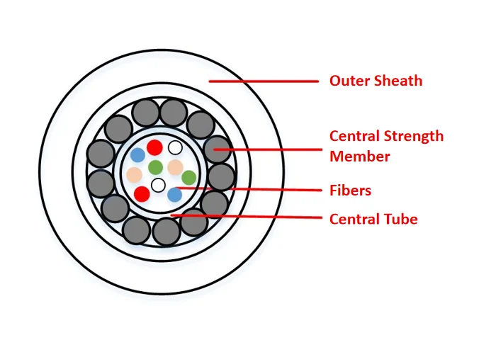
3.3 Central Tube Structure Type:
- Similar to the skeletal structure optical cable, the central tube structure optical cable has a large tube at its center for housing optical fibers—this tube is called a “large sleeve”. The large sleeve contains coated optical fibers, which are placed inside the sleeve without stranding. The strength member layer is wrapped around the large sleeve.
- This type of optical cable features a simple structure and straightforward manufacturing process. It provides better protection for optical fibers than other structural types and has excellent lateral pressure resistance, which can enhance the stability of network transmission. With a small cross-sectional area and light weight, it is particularly suitable for aerial laying. The number of fibers in the central tube is flexible, but the total number of fibers in the cable should not be excessively large.
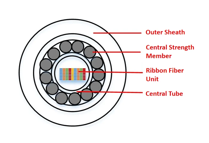
3.4 Ribbon Structure Type:
Ribbon structure optical cables get their name from the fact that they house ribbon fiber units. A ribbon fiber unit refers to a rectangular fiber assembly composed of several stacked layers of ribbon fibers.
- Placing the ribbon fiber unit into a large sleeve results in a central tube ribbon optical cable;
- Placing it into a skeleton groove forms a skeletal ribbon optical cable;
- Placing it into a fiber sleeve and stranding it around a central strength member creates a stranded ribbon optical cable.
Ribbon structure optical cables feature a small volume, which can increase the fiber density in the cable and accommodate more fiber cores—for example, 320 to 3,456 cores. They are suitable for the rapidly developing fiber access networks at present.
3.5 Little Knowledge:
The typical structure of an optical fiber from the inside out is core → cladding → coating (i.e., cladding layer). The core parts are the core and the cladding, which together form the optical fiber and enable the transmission of optical signals. The coating mainly provides mechanical protection for the optical fiber and can be divided into primary coating and secondary coating. According to the different structures of the secondary coating, optical fibers can be divided into tight-buffered fibers, loose-buffered fibers, and ribbon fibers.
- In a tight-buffered fiber, the primary coating and the secondary coating are closely attached, and there is no gap between the two layers. Therefore, the primary-coated fiber cannot move freely within the secondary coating, and the cross-sections of the two layers are concentric.
- In a loose-buffered fiber, the primary coating and the secondary coating are only in contact, and there is a gap between them. The gap is usually filled with water-blocking grease. Therefore, the primary-coated fiber can move freely within the secondary coating.
- A ribbon fiber is an optical fiber in which bare fibers are arranged in a row to form a ribbon shape.
3.6 Need help narrowing it down further? Match the cable to your use case:
| Optical Cable Structure | Structural Features | Performance Features | Recommended Installation Methods |
|---|---|---|---|
| Stranded Type | Optical fibers are stranded around the central strength member. | Easy to manufacture; good mechanical and environmental performance; relatively few fibers. | Direct burial, duct installation, aerial laying, and underwater laying. |
| Skeletal Type | Optical fibers are placed in the grooves of the skeleton. | Complex to manufacture; excellent protection performance, good lateral pressure resistance; compact structure, small cable diameter; relatively many fibers. | Duct installation. |
| Central Tube Type | Optical fibers are placed in the central large sleeve. | Simple structure, the simplest manufacturing process, low cost; flexible number of fibers, but the number of fibers in the cable should not be too large. | Aerial laying. |
| Ribbon Type | Optical fibers are placed in sleeves, skeletons, or large sleeves in the form of ribbon fiber units. | Optical cable with the highest space utilization; can accommodate large-capacity fibers. | Direct burial, duct installation. |
| Optical Cable Name | Recommended Optical Cable Structure | Performance Requirements | Applicable Scope |
|---|---|---|---|
| Customer Optical Cable | Central Tube Type, Ribbon Type | High Density, Broad Bandwidth, Medium and Low Loss | Computer Networks, Fiber to the Home (FTTH) |
| Metropolitan Optical Cable | Stranded Type, Ribbon Type | Low Loss, Broad Bandwidth | Intra – city |
| Long – haul Optical Cable | Central Tube Type | Low Loss, Broad Bandwidth | Inter – city, Long – haul |
| Submarine Optical Cable | Stranded Type | Low Loss, Broad Bandwidth, High Mechanical Performance, High Reliability | Submarine |
4. Decoding Cable Models: How to Read the Labels

Ever looked at a cable label like “GYFTA53” and felt confused? You’re not alone. In China (a top manufacturing hub), cable models follow the YD/T 908-2011 standard—and they’re packed with useful info. Here’s how to break them down:
A full model has three parts: Type + Specification + Special Features (Special Features are optional). Let’s focus on the “Type” part, which tells you 90% of what you need to know:
4.1 Breakdown of the “Type” Code
The Type code has 5 sections: [Category] [Strength Member] [Structure] [Jacket] [Outer Layer]
Example: Let’s decode “GYFTA53” (a common outdoor cable):
| Section | Code | Meaning |
|---|---|---|
| 1. Category | GY | Outdoor/field communication cable (most common for infrastructure) |
| 2. Strength Member | F | Non-metallic (good for areas with corrosion or lightning risk) |
| 3. Structure | T | Filled design (waterproof); no other symbols = stranded layer + loose tube |
| 4. Jacket | A | Aluminum-polyethylene bonded jacket (moisture barrier) |
| 5. Outer Layer | 53 | 5 = Corrugated steel armor; 3 = Polyethylene outer coat (for direct burial) |
4.2 Quick Reference: Key Codes You’ll See
| Type | Ⅰ | Ⅱ | Ⅲ | Ⅳ | Ⅴ |
|---|---|---|---|---|---|
| Item | Classification | Strength Member | Structural Feature | Jacket | Outer Sheath |
| Specification | Ⅰ | Ⅱ |
| Item | Optical Fiber Specification | Core Wire Specification |
| TYPE I (Classification)Designation Code | Meaning |
|---|---|
| GY | Outdoor (Field) Optical Cable for Telecommunications |
| GYW | Miniature Outdoor Optical Cable for Telecommunications |
| GYC | Miniature Outdoor Optical Cable for Telecommunications with Air – Blown Installation |
| GYL | Outdoor Optical Cable for Telecommunications Laid in Micro – trenches on Pavement |
| GYP | Outdoor Rodent – proof Optical Cable for Telecommunications in Drainage Pipes |
| GJ | Indoor (Central Office) Optical Cable for Telecommunications |
| GJC | Miniature Indoor Optical Cable for Telecommunications with Air – Blown Installation |
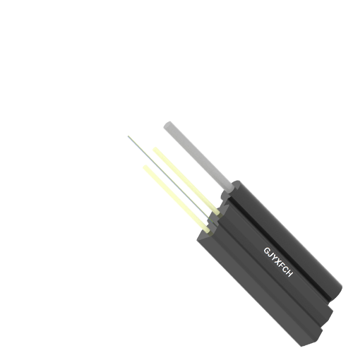
| GJX | Indoor Drop Optical Cable for Telecommunications |
| GJY | Indoor – Outdoor Optical Cable for Telecommunications |
| GJYX | Indoor – Outdoor Drop Optical Cable for Telecommunications |
| GH | Submarine Optical Cable for Telecommunications |
| GM | Mobile Optical Cable for Telecommunications |
| GS | Submarine Optical Cable for Telecommunications |
| GT | Special Optical Cable for Telecommunications |
| TYPE II (Strength Member)Designation Code | Meaning |
|---|---|
| No symbol | Metallic strength member |
| F | Non – metallic strength member |
| TYPE III (Structural Feature)Designation Code | Structural Feature | Meaning |
|---|---|---|
| No symbol | Cable Core Fiber Structure | Discrete fiber structure |
| D | Cable Core Fiber Structure | Fiber ribbon structure |
| No symbol | Secondary Coating Structure | Fiber loose tube coating structure or non-coating structure |
| S | Secondary Coating Structure | Fiber bundle structure |
| J | Secondary Coating Structure | Fiber tight tube coating structure |
| No symbol | Loose Tube Material | Plastic loose tube or no loose tube |
| M | Loose Tube Material | Metallic loose tube |
| No symbol | Cable Core Structure | Stranded structure |
| G | Cable Core Structure | Skeleton groove structure |
| X | Cable Core Structure | Central tube structure |
| No symbol | Water-blocking Structure | All-dry or semi-dry structure |
| T | Water-blocking Structure | Filled structure |
| No symbol | Load-bearing Structure | Non-self-supporting structure |
| C | Load-bearing Structure | Self-supporting structure |
| No symbol | Messenger Wire Material | Metallic strength messenger wire or no messenger wire |
| F | Messenger Wire Material | Non-metallic strength messenger wire |
| No symbol | Cross-section Shape | Circular shape |
| E | Cross-section Shape | Elliptical shape |
| B | Cross-section Shape | Elliptical shape |
| 8 | Cross-section Shape | Figure-eight shape |
| TYPE IV (Jacket)Designation Code | Meaning |
|---|---|
| Y | Polyethylene (PE) sheath |
| V | Polyvinyl Chloride (PVC) sheath |
| U | Polyurethane (PU) sheath |
| H | Low Smoke Zero Halogen (LSZH) sheath |
| A | Aluminum-Polyethylene Bonded Sheath (abbreviated as A sheath) |
| S | Steel-Polyethylene Bonded Sheath (abbreviated as S sheath) |
| F | Non-metallic Fiber Reinforced-Polyethylene Bonded Sheath (abbreviated as F sheath) |
| W | Steel Wire Armored Steel-Polyethylene Bonded Sheath (abbreviated as W sheath) |
| L | Aluminum sheath |
| G | Steel sheath |
When an optical cable is equipped with an outer sheath (i.e., Type V in the designation system), the outer sheath may include part or all of the bedding layer, armor layer, and outer jacket. Therefore, Type V is represented by two groups of numbers. Each group of numbers may consist of 1 or 2 digits. For the meanings of Type V (sheath) in the designation system, please refer to the table below:
| TYPE V (Outer Sheath) | |||
|---|---|---|---|
| First Group (Armor Layer) | Meaning | Second Group (Outer Jacket/Coating) | Meaning |
| 0 | No armor layer | No symbol | No outer jacket/coating |
| 1 | Steel tube | 1 | Fiber outer coating |
| 2 | Double steel tape lapping | 2 | Polyvinyl Chloride (PVC) jacket |
| 3 | Single thin round steel wire | 3 | Polyethylene (PE) jacket |
| 33 | Double thin round steel wires | 4 | Polyethylene (PE) jacket with nylon coating |
| 4 | Single thick round steel wire | 5 | Polyethylene (PE) protective jacket |
| 44 | Double thick round steel wires | 6 | Flame-retardant polyethylene (FR-PE) jacket |
| 5 | Corrugated steel tape | 7 | Nylon coating with polyethylene (PE) jacket |
| 6 | Non-metallic wire | – | – |
| 7 | Non-metallic tape | – | – |
The optical fiber specification is composed of the number of optical fibers and the optical fiber type. For the optical fiber type, please refer to the optical fiber product classification table. The number of optical fibers is represented by a digit indicating the actual effective number of optical fibers of the same type in the cable. The optical fiber type designation shall comply with the provisions of GB/T 12357 and GB/T 9771. For the optical fiber type, please refer to the table below:
| Specification I,II | |||
|---|---|---|---|
| Multimode Optical Fiber | Meaning | Single-mode Optical Fiber | Meaning |
| A1a.1 | Silica graded-index multimode optical fiber | B1.1 | Silica non-dispersion-shifted single-mode optical fiber (i.e., G.652.A / G.652.B fiber) |
| A1a.2 | Silica graded-index multimode optical fiber | B1.2 | Silica cut-off wavelength-shifted single-mode optical fiber (i.e., G.654 fiber) |
| A1a.3 | Silica graded-index multimode optical fiber | B1.3 | Silica non-dispersion-shifted single-mode optical fiber with extended wavelength band (i.e., G.652.C fiber) |
| A1b | Silica graded-index multimode optical fiber | B2 | Silica dispersion-shifted single-mode optical fiber (i.e., G.653 fiber) |
| A1d | Silica graded-index multimode optical fiber | B4a | Silica non-zero dispersion-shifted single-mode optical fiber (i.e., G.655.A fiber) |
| A2a~A2c | Silica step-index multimode optical fiber | B4b | Silica non-zero dispersion-shifted single-mode optical fiber (i.e., G.655.B fiber) |
| A3a~A3c | Silica graded-index, plastic-clad multimode optical fiber | B4c | Silica non-zero dispersion-shifted single-mode optical fiber (i.e., G.655.C fiber) |
| A4a~A4d | Step-index plastic optical fiber | B4d | Silica non-zero dispersion-shifted single-mode optical fiber (i.e., G.655.D fiber) |
| A4e | Graded or multi-step index plastic optical fiber | B4e | Silica non-zero dispersion-shifted single-mode optical fiber (i.e., G.655.E fiber) |
| A4f~A4h | Graded-index plastic optical fiber | B5 | Silica non-zero dispersion optical fiber for wide wavelength band transmission (i.e., G.656 fiber) |
| – | – | B6a1 | Bend-loss insensitive optical fiber for access networks (i.e., G.657.A1 fiber) |
| – | – | B6a2 | Bend-loss insensitive optical fiber for access networks (i.e., G.657.A2 fiber) |
| – | – | B6b2 | Bend-loss insensitive optical fiber for access networks (i.e., G.657.B2 fiber) |
| – | – | B6b3 | Bend-loss insensitive optical fiber for access networks (i.e., G.657.B3 fiber |
5. Emerging Cable Technologies to Watch
Procurement isn’t just about today—you need cables that last through 5G, IoT, and future upgrades. Here are three innovations worth considering:
5.1 Eco-friendly Optical Cable
Eco-friendly optical cables are primarily designed from an environmental protection perspective to address the issue of non-environmentally friendly materials in conventional cables. For instance, PVC releases toxic gases when burned, and some cable stabilizers contain lead. Such cables are mainly used indoors, in buildings, and for household applications. Currently, some companies have developed new materials for these cables, such as halogen-free flame-retardant plastics.
5.2 Nano-technology Optical Cable
Nano-technology optical cables adopt nano-materials (e.g., nano optical fiber coating, nano optical fiber grease, nano-polyethylene for cable sheaths, and nano-PBT for fiber sheaths). They leverage the numerous excellent properties of nano-materials, such as enhanced mechanical impact resistance of the cable.
5.3 Micro Optical Cable
Micro optical cables are mainly developed to match the application of pneumatic or hydraulic installation and construction systems. Various micro optical cable structures have been designed and put into use, which require a specific coefficient between the cable and the duct, as well as accurate weight and appropriate rigidity of the cable. Micro optical cables, together with automated installation methods, are intended to meet the needs of future access networks—especially for cabling in the structured cabling system of customer premises networks and the intelligent ducts of smart buildings.
6. Final Checklist for Smart Procurement
Before you sign off on an order, confirm these 5 points:
- Project Match: Does the cable type (stranded/ribbon/etc.) fit the installation method (aerial/ducts)?
- Environment Fit: Is the jacket/armor right for weather, corrosion, or rodent risk?
- Fiber Specs: Do the fiber count and type (single-mode/multi-mode) support your speed/distance needs?
- Compliance: Meets YD/T 908-2011 (or local standards) and eco-requirements?
- Future-Proofing: Can it handle upgrades (e.g., higher bandwidth for 5G)?